 BBELC
BBELC
How Isolation Transformers Work: 5 Functions Defined
45Discover How Isolation Transformers Work. Learn The Definition, 5 Critical Functions, And Buyer Pitfalls.
View details
Search the whole station
A power transformer operates at constant peak loads (100% capacity) within high-voltage transmission networks (typically above 33kV) to minimize I²R transmission losses. A distribution transformer steps down voltage to consumer levels (below 33kV) and handles highly variable daily loads, achieving maximum efficiency at exactly 50% to 70% of its rated capacity.
Grid modernization completely destroys old sizing calculations. The 2026 Department of Energy (DOE) efficiency mandates, coupled with the violent load spikes from EV charging networks, require engineers to stop treating these assets interchangeably. We are going to rip apart the exact 2026 technical specs, material shifts, and procurement traps defining the power vs distribution transformer debate right now.
Understanding the difference between power and distribution transformer engineering comes down to load profile anticipation. Power transformers are designed to run hot and heavy continuously. Distribution transformers spend most of their lives idling, waiting for the evening residential peak.
TuPian ChaRu (Prompt: Insert a high-contrast infographic showing a flat load curve for a power transformer alongside a highly volatile, jagged daily load curve for a distribution transformer, annotated with 2026 efficiency target zones.)
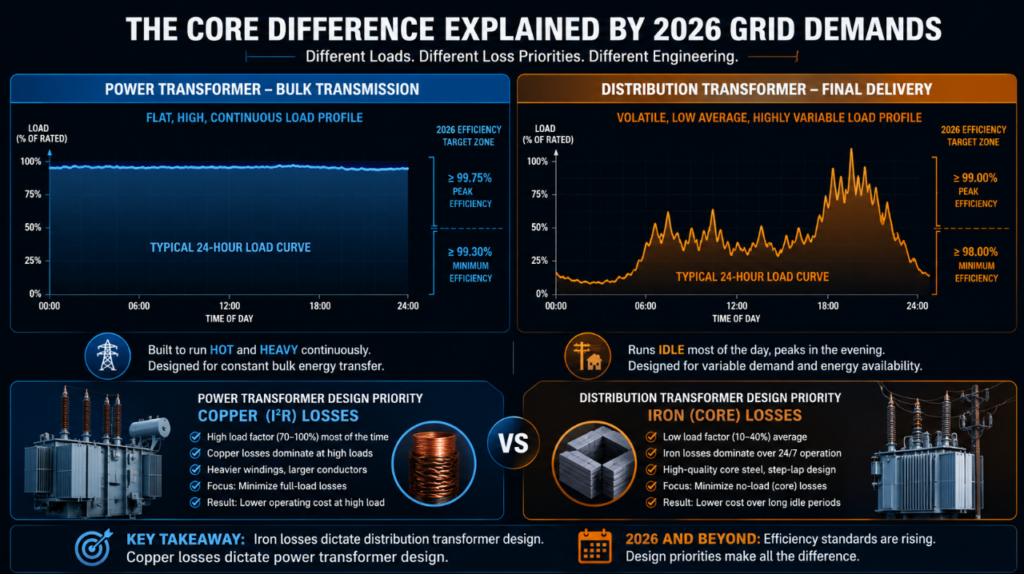
Iron losses dictate distribution transformer design, while copper losses dictate power transformer design. Because distribution units are energized 24/7 but only fully loaded occasionally, manufacturers engineer the core to minimize no-load (iron) losses. Power transformers constantly transmit massive bulk energy, forcing designers to prioritize heavy copper windings to limit full-load (copper) losses.
Integrating modern solar microgrids changes this binary equation. A traditional power transformer and distribution transformer setup assumes one-way power flow. Today, bi-directional energy flow from rooftop solar pushes distribution units to handle reverse currents, requiring advanced tap changers previously reserved only for substation-class power transformers.
Selecting the right equipment requires abandoning basic nameplate ratings and adopting the 3-T Matrix: Topology, Thermal, and Telemetry. Basic voltage matching leads to catastrophic equipment failure under modern harmonic loads.
Location determines fault current exposure. Power transformers sit at generation and transmission nodes, requiring massive short-circuit withstand capabilities (up to 2 seconds). Distribution transformers sit at the grid edge. You must spec them based on local short-circuit MVA available, which is significantly lower but highly prone to lightning and switching surges.
Load characteristics define cooling requirements. Specifying ONAN (Oil Natural Air Natural) for a distribution transformer feeding an EV charging hub will cause rapid insulation degradation. High-capacity power transformers rely on ODAF (Oil Directed Air Forced) systems. You must match the thermal time constant of the transformer oil to the expected peak duration of your specific consumer load.
Predictive maintenance is a hard requirement in 2026. Substation power transformers require dissolved gas analysis (DGA) monitors and fiber optic temperature sensors in the windings. Distribution units now require at least smart meters and basic IoT pressure sensors to detect abnormal off-gassing before a pole-top explosion occurs.
Comparing raw specifications reveals exactly how regulatory bodies force manufacturers to alter transformer DNA.
| Specifications | Power Transformer | Distribution Transformer |
|---|---|---|
| Voltage | Typically 66 kV–765 kV+ | Typically 240 V–35 kV |
| Efficiency Peak | 99.2–99.8%, optimized near full load | 98.0–99.2%, optimized across variable load cycles |
| Cooling Methods | ONAN, ONAF, OFAF, OFWF (oil-based and forced cooling) | ONAN, dry-type air-cooled, or sealed liquid-filled |
| Core Material (CRGO vs. Amorphous) | Primarily CRGO steel for mechanical strength and magnetic stability | Increasing use of amorphous metal cores to reduce no-load losses |
| Flux Density | Higher, typically 1.6–1.8 Tesla | Lower, typically 1.3–1.6 Tesla for efficiency and thermal control |
| Typical Lifespan under EV Loads | 35–50 years with grid-level load balancing and scheduled maintenance | 20–30 years, depending on charging concentration and overload cycles |
The 2026 DOE mandates push distribution transformers heavily toward Amorphous Metal Cores (AMC). AMC reduces no-load losses by up to 70% compared to traditional Cold-Rolled Grain-Oriented (CRGO) silicon steel. Power transformers still strictly utilize high-grade laser-domain refined CRGO because amorphous steel lacks the structural rigidity needed to withstand the immense mechanical forces of a transmission-level short circuit.
Distribution transformers operate at lower magnetic flux densities (around 1.5 to 1.6 Tesla). Operating below the saturation knee minimizes idle excitation current. Power transformers operate at much higher flux densities (1.7 to 1.8 Tesla) to reduce the physical size and cost of the massive core, accepting higher excitation currents as an acceptable trade-off for continuous full-load operation.
Insulation coordination defines equipment longevity. Power transformers utilize complex interleaved or shielded windings to distribute lightning impulse voltages evenly across the massive coils. Distribution transformers employ standard layer windings but rely heavily on robust Kraft paper insulation and modern bio-dielectric fluids (like natural ester oils) to handle frequent, localized overvoltage transients.
Procurement managers actively destroy capital budgets by misapplying legacy purchasing formulas to modern grid hardware. I see millions wasted annually due to fundamental misunderstandings of load profiles.
Slapping a standard 500 kVA distribution transformer on a new DC Fast Charging station guarantees premature failure. DC fast chargers create vicious harmonic distortion and immediate, violent load spikes. Standard distribution cores heat up instantly under these conditions. You must specify a “K-factor” rated distribution transformer or a unit with upgraded thermal class insulation (like Nomex) to survive EV infrastructure demands.
Engineers routinely over-size distribution transformers “just to be safe.” This instantly penalizes the facility owner. A transformer running at 15% capacity suffers terrible efficiency because constant iron losses dominate the energy calculation. You must size distribution units so their normal daily peak aligns with the 50-70% optimal efficiency curve dictated by the manufacturer’s test report.
Upgrading the primary substation for the newly expanded Texas Silicon Manufacturing Hub in late 2025 exposed the exact friction point between transmission and distribution. The client initially requested a massive 50 MVA power transformer to step down 138kV directly to 13.8kV for site-wide distribution.
Our engineering team rejected this design. A single massive unit forced the entire facility to absorb massive I²R losses during the plant’s 12-hour low-production night shift.
We deployed a split architecture. We installed two 25 MVA power transformers at the main substation, feeding a secondary loop of twelve 2 MVA high-efficiency amorphous core distribution transformers located directly at the load centers.
This data proves that understanding the precise operational boundary between bulk power delivery and localized load handling dictates the financial viability of industrial microgrids.
Can a power transformer be used as a distribution transformer?
Yes, mechanically, but it is financially ruinous. A power transformer has massive iron losses. Running it at the low, fluctuating loads typical of a distribution network means you will pay a massive energy penalty for continuous core excitation while utilizing a fraction of its capacity.
Why is the efficiency of a distribution transformer calculated differently?
We calculate distribution efficiency using “All-Day Efficiency” (energy output in kWh over 24 hours divided by energy input). We calculate power transformer efficiency using simple commercial efficiency (Power out / Power in) at full load. The 24-hour metric accounts for the distribution unit’s prolonged idle periods.
What is the difference in tap changers between the two?
Power transformers feature On-Load Tap Changers (OLTC) to regulate grid voltage dynamically without interrupting power flow. Distribution transformers typically feature Off-Circuit Tap Changers (OCTC), requiring technicians to de-energize the unit to manually adjust the voltage ratio for seasonal changes.
How do 2026 DOE regulations affect distribution transformer pricing?
The mandate for amorphous metal cores increases the physical size and upfront manufacturing cost of distribution transformers by roughly 15-20%. The payback period occurs within 3 to 5 years through drastically reduced no-load energy losses.
What happens if a distribution transformer is overloaded by solar feed-in?
Reverse power flow from rooftop solar raises the secondary side voltage. Without an automatic voltage regulator or an OLTC, the distribution transformer pushes overvoltage back into the local grid, causing inverters to trip and accelerating the degradation of the transformer’s insulating oil.
Why do power transformers use forced cooling while distribution units do not?
Power transformers generate intense, concentrated heat due to 100% continuous loading, requiring pumps and fans (OFAF) to physically push oil through external radiators. Distribution units naturally dissipate heat via convection (ONAN) because their loads drop frequently, giving the oil time to cool passively.
Discover How Isolation Transformers Work. Learn The Definition, 5 Critical Functions, And Buyer Pitfalls.
View detailsDistribution Transformer Parts And Functions: Master Strict Loading Rules And Thermal Limits For Site Engineers.
View detailsOptimize Power Transformer Operation And Maintenance To Extend Life Expectancy And Defer CAPEX Replacements.
View detailsBoost 2026 ROI With A Specialty Solar Power Inverter Transformer. Prevent Thermal Fatigue And Defeat Harmonic Heat.
View detailsPlease fill in the arithmetic result.
The calculation is incorrect, please fill it in again.