 BBELC
BBELC
How Isolation Transformers Work: 5 Functions Defined
45Discover How Isolation Transformers Work. Learn The Definition, 5 Critical Functions, And Buyer Pitfalls.
View details
Search the whole station
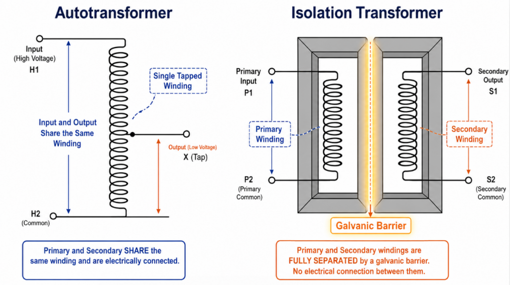
Autotransformers use a single continuous winding to step voltage up or down, offering high efficiency and a smaller footprint, but they provide zero electrical separation between the input and output. Isolation transformers utilize completely separate primary and secondary windings, establishing absolute galvanic isolation to block common-mode noise, eliminate ground loops, and protect sensitive loads from grid faults. Selecting the wrong unit for a modern high-frequency industrial environment leads to immediate code violations and catastrophic equipment failure.
You cannot fix a ground loop issue with an autotransformer, and you cannot rely on a standard isolation transformer to correct a drooping grid voltage. The 2026 hardware landscape—dominated by SiC (Silicon Carbide) inverters, edge data centers, and EV fast-charging hubs—demands aggressive power quality control. System integrators face strict NEC and IEEE mandates that penalize poor transformer specification. The technical facts below dictate exactly which unit your facility requires.
The fundamental difference between autotransformer and isolation transformer architecture determines your system’s safety threshold. Autotransformers share a common physical connection (usually the neutral line) between the source and the load. Isolation transformers sever that physical connection entirely, relying purely on magnetic flux across an air gap to transfer power.
An autotransformer saves you up to 40% in weight, copper, and CAPEX. Electrical engineers specify them exclusively for bulk voltage matching—such as stepping a 480V commercial supply down to 400V for a heavy CNC motor. A fault on the primary side of an autotransformer transfers directly to your secondary load. A broken neutral connection sends the full high-line voltage directly into your sensitive control boards, instantly destroying them.
Isolation transformers provide a firewall. The separation of windings creates a “new neutral” bonded to the local ground on the secondary side. This configuration blocks DC injection, dampens high-frequency harmonic noise generated by modern variable frequency drives (VFDs), and protects human operators from severe shock hazards if a ground fault occurs.
B2B buyers consistently waste procurement budgets by over-specifying transformers or under-protecting their assets. Apply this P.I.C. (Protection, Isolation, Conditioning) framework to match hardware to your exact site anomaly:
| Equipment Type | Galvanic Isolation | Voltage Regulation | Noise Filtering | Cost Multiplier |
|---|---|---|---|---|
| Autotransformer | No | Moderate; voltage step-up/step-down only | Low | 1.0× |
| Isolation Transformer | Yes | Low to moderate; depends on design | High; strong common-mode noise reduction | 1.5× – 2.5× |
| Voltage Stabilizer | Usually no | High; designed for automatic voltage correction | Low to moderate | 1.5× – 3.0× |
| Power Conditioner | Optional; depends on model | Moderate to high | High; designed to filter noise, spikes, and transients | 2.0× – 4.0× |
A power conditioner actively cleans incoming dirty power, while an isolation transformer merely provides passive electrical separation. Procurement managers often confuse the two terms.
When evaluating power conditioner vs isolation transformer, look at the internal components. A true industrial power conditioner encases a high-quality isolation transformer but adds robust surge suppression networks, RFI/EMI high-frequency capacitors, and sometimes active voltage regulation circuits.
You install a standalone isolation transformer to establish a separately derived system and break ground loops. You install a power conditioner when you must actively eliminate voltage spikes, harmonic distortion, and electrical transients before they reach highly sensitive medical imaging equipment or semiconductor fabrication tools.
Voltage stabilizers maintain a strict output voltage window during aggressive input voltage fluctuations, but they do not isolate your equipment from the grid. Isolation transformers block common-mode noise and ground loops but pass input voltage sags directly through to your load.
Understanding the difference between isolation transformer and voltage stabilizer prevents costly downtime. A manufacturing plant suffering from 15% voltage dips (brownouts) will gain zero benefit from a standard isolation transformer. The output voltage will drop exactly as the input voltage drops, causing PLCs to reset and shutting down the production line. A servo-controlled or static voltage stabilizer corrects that dip within milliseconds.
Conversely, installing a basic voltage stabilizer does nothing to prevent common-mode electrical noise from traversing the line and corrupting data signals in server racks. If you face both severe voltage swings and heavy electrical noise, engineering specifications dictate installing a voltage stabilizer feeding into an isolation transformer, or purchasing a comprehensive active power conditioner.
Relying on outdated transformer guidelines destroys modern equipment. In early 2026, a major logistics company in Texas installed a 400kW DC fast-charging fleet hub. The system integrator needed to step down a 480V grid connection to feed the 400V chargers. To minimize footprint and cut initial costs by $12,000, they installed a massive autotransformer.
The failure occurred 45 days later. A high-frequency switching fault within one of the SiC chargers injected significant DC current back into the AC line. Because the autotransformer lacked galvanic isolation, this DC current bypassed the local breakers, traveled straight back into the facility’s main switchgear, and saturated the primary distribution transformer.
The resulting failure destroyed the switchgear and caused a multi-day outage. Total damages exceeded $350,000. An isolation transformer would have contained that DC injection at the secondary winding, triggering a localized breaker trip and protecting the upstream infrastructure. Upfront CAPEX savings on autotransformers often mask massive operational risks in environments generating heavy harmonic or DC noise.
What is the main difference between autotransformer and isolation transformer?
An autotransformer uses a single winding for both input and output, offering zero electrical isolation. An isolation transformer uses completely separate primary and secondary windings, establishing a physical barrier (galvanic isolation) that blocks electrical noise and ground loops.
When should I specify an autotransformer instead of an isolation transformer?
Specify an autotransformer when you only need to step voltage up or down, your input power is clean, you have no ground loop issues, and you need to minimize the physical size and cost of the installation.
Can an isolation transformer fix low voltage from the utility grid?
No. An isolation transformer has a fixed turns ratio. If the utility grid voltage drops by 10%, the output voltage of the isolation transformer also drops by 10%. You need a voltage stabilizer to correct voltage sags.
What is the difference between isolation transformer and voltage stabilizer?
An isolation transformer separates electrical circuits for safety and noise reduction but does not correct voltage levels. A voltage stabilizer actively monitors and corrects input voltage fluctuations to provide a steady output, but typically provides zero electrical isolation.
In the debate of power conditioner vs isolation transformer, which is better for IT racks?
A power conditioner is superior for IT racks. While an isolation transformer only stops ground loops and common-mode noise, a power conditioner includes an isolation transformer plus surge suppression and active noise filters to handle transients that destroy server power supplies.
Does a shared neutral wire pose a danger in autotransformers?
Yes. Because the primary and secondary circuits share the same neutral ground path, any fault on the high-voltage side can travel directly to the low-voltage side, presenting a severe shock hazard and risking destruction of the connected load.
Discover How Isolation Transformers Work. Learn The Definition, 5 Critical Functions, And Buyer Pitfalls.
View detailsPower Transformer Type Test: Learn How To Check Performance, Audit Factory Data, And Avoid Hidden Defects.
View detailsHow To Test A Power Transformer And Tell If Yours Is Bad. Master Pro Multimeter Tests And Avoid Phantom Voltage.
View detailsFind A Pad-Mounted Distribution Transformers Factory. Secure DOE 2016 And IEEE Units In 20 Weeks. Bypass Fake OEMs.
View detailsPlease fill in the arithmetic result.
The calculation is incorrect, please fill it in again.