 BBELC
BBELC
Fuse Rating of Distribution Transformer & OLTC Setup: The Advanced Engineering Guide
18Master Fuse Rating Of Distribution Transformer & Oltc Distribution. Use Our 3-Node Sizing Guide To Stop Trips.
View details
Search the whole station
Distribution transformer parts and functions strictly dictate the loading rules and maximum thermal thresholds every site engineer must enforce. The structural integrity of the core, windings, and cooling mechanisms determines the unit’s thermal inertia, which directly limits how much cyclic or emergency load the transformer can handle before the solid insulation permanently degrades. Relying solely on static nameplate data causes premature equipment failure and thousands of dollars in lost operational life. Actual load optimization requires matching real-time physical component data with standard IEEE/IEC thermal formulas. We will break down the exact physics, specific component thresholds, and field-tested formulas driving these loading capabilities below.
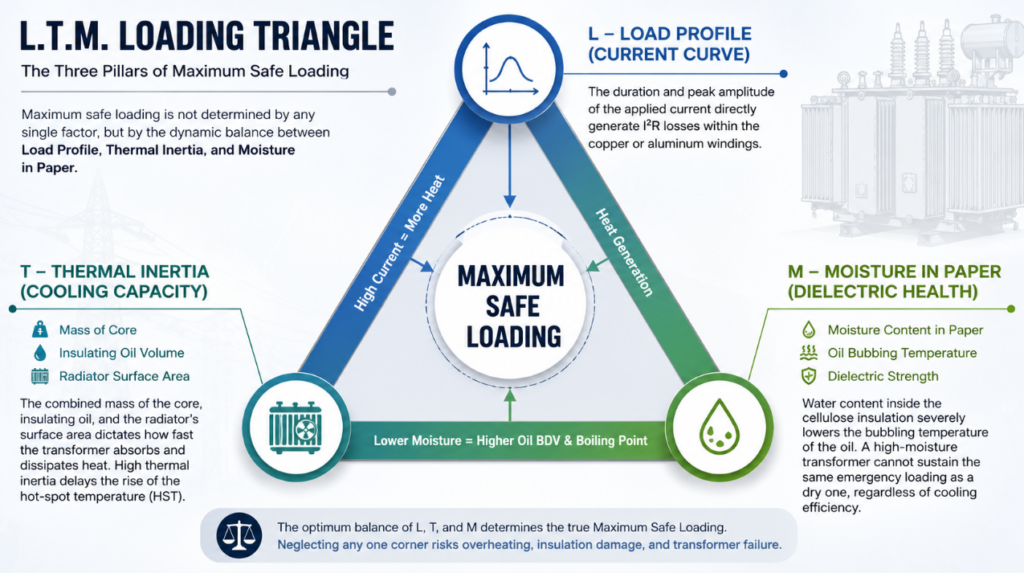
Transformer load capacity is not a static number, but a dynamic equilibrium governed by three physical variables. The L.T.M. Loading Triangle provides a precise mental model for substation engineers determining safe overloads during peak grid demand.
I2RI2R losses within the copper or aluminum windings.“”TuPian ChaRu””
(Insert a custom infographic illustrating the “L.T.M. Loading Triangle”. The triangle should have Load Profile, Thermal Inertia, and Moisture at the three corners, with “Maximum Safe Loading” in the center.)
Every component within a distribution unit plays a direct role in heat generation, heat dissipation, or operational monitoring. Identifying the specific limitation of each part prevents catastrophic thermal runaway during peak hours.
The magnetic core and conductive windings act as the primary heat sources under load conditions. The core, constructed from cold-rolled grain-oriented (CRGO) steel sheets, generates no-load losses (iron losses) due to hysteresis and eddy currents. The windings generate load losses (copper losses) proportional to the square of the load current. Insulation paper wrapping the windings remains the most vulnerable material in the entire unit. When winding hot-spot temperatures exceed 98°C, the Degree of Polymerization (DP) of the cellulose paper drops sharply, halving the paper’s lifespan for every 6°C increase.
The cooling infrastructure physically moves thermal energy away from the critical active components. Mineral oil serves a dual purpose: high dielectric strength to prevent arcing and high thermal conductivity to act as a heat transfer fluid. As the oil heats up, natural convection pushes it upward through the radiators (cooling fins), where atmospheric air dissipates the heat before the cooler oil cycles back to the bottom. The conservator tank accommodates the expansion of this heated oil. Proper loading of distribution transformer units completely depends on the efficiency of this convection cycle. Blocked radiator fins or degraded oil viscosity immediately nullify standard loading curves.
Accessory parts detect early-stage thermal faults caused by improper loading before complete dielectric failure occurs. The Buchholz relay sits between the main tank and the conservator, trapping gases generated when localized overloading causes oil to decompose into hydrogen and methane. The silica gel breather strips moisture from the air pulled into the conservator during load drops (oil contraction). The off-circuit or on-load tap changer (OLTC) adjusts voltage ratios. Intense cyclic loading accelerates mechanical wear on tap changer contacts, making it a primary point of inspection for maintenance contractors.
Calculating the loading of distribution transformer assets requires strict adherence to standard guidelines like IEC 60076-7 or IEEE C57.91. Operating personnel must separate normal operational limits from short-term emergency conditions.
Operating a transformer at its rated continuous power (kVA) at a standard ambient temperature (usually 20°C) results in normal life expectancy. Under these conditions, the winding hot-spot temperature peaks at 98°C (IEC) or 110°C (IEEE, depending on insulation class). Substation operators base base-load distribution planning on these steady-state thermal limits. Continuous loading prevents extreme thermal cycling, which otherwise causes thermal expansion and contraction stresses on winding clamping structures.
Transformers routinely survive cyclic overloading events up to 120% or 130% of their rating, provided the previous load was low and ambient temperatures are favorable. The actual constraint is the relative aging rate (
VV). Field engineers use the Arrhenius equation to calculate this rate based on hot-spot temperature. An emergency overload pushing the hot-spot to 140°C might cause a relative aging rate of 100, meaning one hour of operation at this load consumes 100 hours of the transformer’s baseline operational life. Site engineers accept this accelerated aging only during critical grid restoration, closely monitoring top-oil temperature limits (usually capped at 105°C).
Maintenance contractors frequently misdiagnose the root cause of rapid moisture ingress during high loading cycles. A common field scenario involves finding saturated (pink) silica gel and rapidly degrading oil dielectric strength. The standard response is simply replacing the silica gel.
Expert technicians look at the breather’s bottom oil cup. A low oil level in the sealing cup—or a micro-crack in the breather pipe—creates a bypass channel. Atmospheric air, laden with moisture, gets sucked directly into the conservator during load drops without ever touching the active silica gel. The unit fails the next time it experiences emergency loading because the moisture has drastically lowered the oil’s bubbling temperature. Always pressure-test the breather pipe assembly before authorizing an aging transformer for high-capacity cyclic loads.
Modern utility operators abandon static nameplate limits in favor of Dynamic Thermal Rating (DTR) utilizing Digital Twin sensor logic. Instead of assuming worst-case ambient temperatures, DTR systems pull real-time data from fiber-optic temperature sensors embedded directly in the primary winding. The algorithm calculates exact thermal capacity in real-time, often unlocking 15% to 25% hidden load capacity during winter months or high-wind days. This real-time alignment of distribution transformer parts and functions with advanced telemetry represents the highest standard of grid asset optimization.
Q: What are the primary parts of a distribution transformer?
The core active parts include the magnetic core and windings. The cooling and structural parts consist of the main tank, insulating oil, radiators, and conservator. Protection accessories include the Buchholz relay, silica gel breather, and pressure relief valve.
Q: How do distribution transformer parts and functions dictate loading limits?
The thermal degradation threshold of the insulation paper around the windings strictly sets the loading limit. All cooling parts (oil, radiators) function purely to keep this specific paper below 98°C to prevent rapid loss of operational life.
Q: What is the maximum allowable loading of a distribution transformer?
Continuous loading is limited to 100% of the nameplate kVA at rated ambient temperatures. Short-term emergency loading can push to 130%-150% depending on IEC/IEEE guidelines, provided operators accept accelerated insulation aging and strict top-oil temperature caps.
Q: How does ambient temperature affect transformer loading rules?
Lower ambient temperatures increase the thermal gradient between the radiators and the air, improving heat dissipation. A transformer operating in a 0°C environment can sustain a much higher cyclic load without exceeding its hot-spot limit compared to operating at 40°C.
Q: What happens if a distribution transformer is continuously overloaded?
Continuous severe overloading boils the insulating oil, creates trapped gas bubbles, drastically lowers dielectric strength, and brittles the cellulose insulation paper. A minor short-circuit downstream will shatter the brittle windings, causing a catastrophic blowout.
Q: Why is moisture a critical factor in transformer loading capacity?
Moisture trapped in the solid insulation lowers the vaporization temperature of the oil. During heavy loads, moisture turns to steam, creating conductive bubbles within the high-voltage windings, which immediately leads to internal arcing and transformer failure.
Master Fuse Rating Of Distribution Transformer & Oltc Distribution. Use Our 3-Node Sizing Guide To Stop Trips.
View detailsCompare Distribution Vs Power Transformer Specs. Find The Key Difference, Avoid Oversizing And Optimize Costs.
View detailsMaster Ratio And Short Circuit Test Of Power Transformer. Learn How To Test A Power Transformer In The Field.
View detailsDiscover The Key Difference Between Isolation Transformer And Step Down Or Up Models To Prevent Equipment Failures.
View detailsPlease fill in the arithmetic result.
The calculation is incorrect, please fill it in again.