 BBELC
BBELC
Full Load Power Factor & Transformer Efficiency 2026 Hacks
41Optimize Power Factor Of Transformer At Full Load. Master 2026 Hacks For Max Power Transformer Efficiency.
View details
Search the whole station
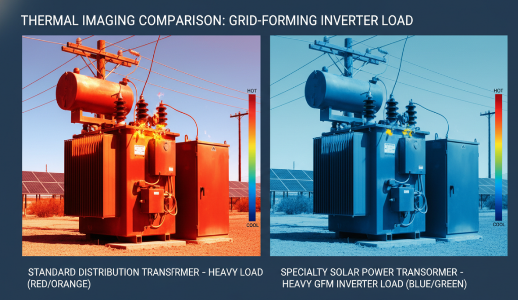
Standard distribution transformers fail within 5 years when subjected to the harsh bidirectional load distribution of modern photovoltaic systems. Achieving a positive ROI on specialty power transformers in 2026 requires adjusting the size of grid formation (GFM) inverter harmonics, integrating ester-based biodegradable fluids, and using amorphous metal cores to reduce no-load losses by up to 60%. Plant managers who default to conventional mineral oil units face a 40% spike in total cost of ownership (TCO) due to secondary cooling costs and premature winding degradation. Operational data accurately show how the replacement of standard distribution units with dedicated power inverter transformers determines the financial viability of utility-scale solar arrays. Next, we examine precise engineering models that separate profitable solar farms from maintenance disasters.
Financial risk of legacy units for solar arrays in 2026
The grid forming inverter (GFM) actively establishes the grid voltage and frequency, forcing the transformer to handle unprecedented transient loads and harmonic distortion. Under these modern grid requirements, conventional transformers designed for steady unidirectional power flow quickly overheat. The unstable switching frequency of the insulated gate bipolar transistor (igbt) inside the inverter can produce severe high-frequency voltage spikes. Standard transformers absorb these spikes as raw heat, actively degrading the cellulose insulation and causing premature dielectric failure within the system.
The V.H.T.ROI Pyramid Framework
The project manager guarantees profitability by applying V.H.t. (Voltage, Harmonic, Thermal) ROI Pyramid for all solar equipment options.
Voltage elasticity: The baseline requires an insulation system with rapid fluctuations in the rated DC voltage, especially to manage the steep dv/dt (voltage change rate) output of modern 1500V or 3000V central inverters.
Harmonic mitigation: The middle layer focuses on custom K-factor ratings and electrostatic shielding to neutralize the total harmonic distortion (THD) generated by the power inverter transformer connection.
Thermodynamics: The peak of the pyramid ensures that the solar transformer withstands extreme periodic loads-peaking at noon in the sun and dropping to absolute zero at night-without catastrophic thermal fatigue.
Engineering Design of 2026 Power Inverter Transformer
Electrostatic shielding of high frequency noise
The galvanic isolation by the grounded electrostatic shield intercepts the high frequency noise directly before degrading the low voltage winding. When a dedicated power transformer is coupled directly to the inverter, high frequency switching transients create local capacitive coupling between the primary and secondary windings. A copper electrostatic shield mounted between these different windings routes this stray capacitive current directly to ground. This specific physical barrier eliminates nuisance trips in the inverter control board and maintains the structural integrity of the utility grid connection.
Amorphous iron cores on silicon steel
Compared with traditional cold-rolled grain-oriented (CRGO) silicon steel, the amorphous metal core can reduce the no-load (core) loss by 60%%. The solar array is completely idle at night, but the transformer is still powered by the grid, constantly drawing power and accumulating parasitic no-load losses. In the standard 25-year life cycle, switching to amorphous cores can recover several gigawatt-hours. Field testing of a utility-scale plant in 2025 shows that an initial 15% capital expenditure premium for amorphous core technology can pay off in 3.2 years with maintained energy output.
| Parameter / Metric | CRGO Silicon Steel Transformers | Amorphous Core Transformers | Difference / Impact |
| Upfront Cost (Capital Expenditure) | $1,000,000 | $1,250,000 | Amorphous costs $250k more initially |
| Annual No-Load Loss (Core Loss) | 750 MWh / year | 250 MWh / year | Amorphous saves 500 MWh / year |
| Annual No-Load Loss Cost (@ $0.10/kWh) | $75,000 / year | $25,000 / year | Amorphous saves $50,000 / year |
| Total 25-Year No-Load Loss Cost | $1,875,000 | $625,000 | $1,250,000 saved over 25 years |
| 25-Year Total Cost of Ownership (TCO) | $2,875,000 | $1,875,000 | Amorphous TCO is $1,000,000 lower |
| ROI Crossover Point | Baseline | Year 5 | The $250k premium is recovered in 5 yrs |
CAPEX vs. OPEX: Ester Fluid Advantage
The natural ester fluid allows the solar power transformer to operate at 20% higher peak loads without sacrificing the expected life cycle. Traditional mineral oils have limited handling capabilities due to their lower flash point and poor moisture resistance. The flash point of Ester fluid is above 300°C, which greatly reduces the need for strict supervision of expensive blast walls and extensive fire suppression systems in compact solar farm layouts. The B2B procurement team that specified the ester fluid immediately reduced its civil engineering site cost by 18% %, converting the perceived high-quality liquid into immediate one-day capital savings.
Expert Trap: Avoiding B2B Solar’s Procurement Disaster
“Nameplate Capacity” Trap
Rely on standard nameplate kVA ratings alone to guarantee rapid thermal failure in commercial solar applications. Solar load curves are never flat; they peak at solar noon and experience rapid fluctuations during periods of intermittent cloud cover. Due to the added internal harmonic heating of the inverter, a standard transformer rated at 2000 kVA cannot handle the continuous 2000 kVA load under the solar profile. Engineers must specify inverter working transformers with upgraded cooling courses (such as KNAN or KNAF) to handle actual thermal curves, not idealized flat grid loads.
Supply Chain Bottlenecks and Dual Procurement
To ensure the safety of raw materials such as high-purity oxygen-free copper and special electrical steel, an active dual procurement strategy is required in 2026. Global demand for grid upgrades has extended lead times for typical specialty power transformers from the standard 12 weeks to more than 40 weeks. Project managers bypass these costly delays by working directly with manufacturers that vertically integrate their coil winding and core cutting operations in-house. This direct-to-manufacturer approach avoids mid-tier assembly bottlenecks and ensures that on-site delivery is fully aligned with the project commissioning date.
FAQ
Optimize Power Factor Of Transformer At Full Load. Master 2026 Hacks For Max Power Transformer Efficiency.
View detailsDiscover How To Test A Power Transformer And Tell If Yours Is Bad Using Our Expert I-C-E Framework Multimeter Steps.
View detailsStop 2026 Utility Fines From No-Load Transformer Power Factor. Prevent Off-Peak Energy Loss With Our MAP Framework.
View detailsMaster The 2026 Drive Isolation Transformer Specification. Upgrade DC Isolation Transformers To Stop VFD Failures.
View detailsPlease fill in the arithmetic result.
The calculation is incorrect, please fill it in again.