 BBELC
BBELC
Calculate Transformer Power: Avoid Apparent Power Traps
50Learn Transformer Power Calculation. Avoid Apparent Power Traps And Master The V-A-P Algorithm For Capacity Sizing.
View details
Search the whole station
Power transformer ratings determine the exact thermal, electrical, and operational limits a unit can handle before catastrophic failure. Standard power transformer ratings define capacity in kVA or MVA, voltage levels (primary/secondary), impedance (%Z), and cooling classes (e.g., ONAN/ONAF). The power transformer symbol on a single-line diagram visually dictates the winding connection (like Delta-Wye) and vector group (like Dyn11) necessary for phase synchronization. Relying solely on a static 1990s standard is dangerous today. Modern facilities driving EV chargers and AI data centers require matching the nameplate to dynamic harmonic loads. This 2026 cheat sheet breaks down how to read, specify, and avoid sizing traps using hard engineering data.
Engineers size transformers using the V.I.P.C. logical framework: Voltage, Impedance, Phase, and Capacity. Missing a single variable guarantees system inefficiency or parallel operation failure.
Voltage Ratings and Tap Changers
The primary and secondary voltage ratings dictate the insulation class and core winding ratio. A typical nameplate displays values like 13800V / 415V. Real-world voltage fluctuates. De-energized Tap Changers (DETC) or On-Load Tap Changers (OLTC) adjust the winding ratios by ±2.5% or ±5% per step. You must specify OLTCs for renewable energy tie-ins where grid voltage volatility exceeds 5% daily.
Impedance (%Z) and Short-Circuit Withstand
Impedance limits the maximum fault current that will flow through the transformer during a downstream short circuit. Standard power transformer ratings feature impedance values ranging from 4% to 8% for distribution units, up to 15% for large sub-transmission units. High impedance reduces fault currents, lowering the interrupting rating required for downstream switchgear. Low impedance improves voltage regulation under heavy loads. Parallel operation strictly requires matching the %Z values of both transformers; unmatched impedance causes the unit with lower %Z to hog the load and overheat.
| Base MVA Rating | Standard Voltage Classes | Typical %Z Range | Cooling Class Options |
|---|---|---|---|
| 5 MVA | 13.8 kV / 4.16 kV | 5.0% – 6.5% | ONAN, ONAF |
| 10 MVA | 34.5 kV / 13.8 kV | 6.0% – 7.5% | ONAN, ONAF |
| 25 MVA | 69 kV / 13.8 kV | 7.0% – 8.5% | ONAN, ONAF, OFAF |
| 50 MVA | 115 kV / 34.5 kV | 8.0% – 10.0% | ONAN, ONAF, OFAF |
| 100 MVA | 138 kV / 69 kV | 9.0% – 11.0% | ONAF, OFAF, OFWF |
| 200 MVA | 230 kV / 115 kV | 10.0% – 12.5% | ONAF, OFAF, OFWF |
| 500 MVA | 345 kV / 230 kV | 12.0% – 15.0% | OFAF, OFWF |
Phase, Vector Groups, and Polarity
Vector groups define the phase shift between the primary and secondary windings. A common designation is Dyn11. “D” stands for a Delta primary, “y” for a Wye (star) secondary, “n” for a neutral connection, and “11” indicates the secondary voltage leads the primary by 30 degrees. Connecting a Dyn11 transformer in parallel with a Dyn1 causes a direct short circuit.
Capacity (kVA/MVA) and Cooling Classes
Capacity represents the maximum apparent power the unit can deliver continuously without exceeding its thermal limit (usually 55°C or 65°C temperature rise). Cooling methods drastically alter this capacity. An ONAN (Oil Natural Air Natural) rating of 20 MVA jumps to 26 MVA under ONAF (Oil Natural Air Forced) by simply activating cooling fans.
Schematic drafting requires precise symbols to prevent catastrophic wiring errors. IEC and IEEE/ANSI standards dictate different visual representations for single-line diagrams.
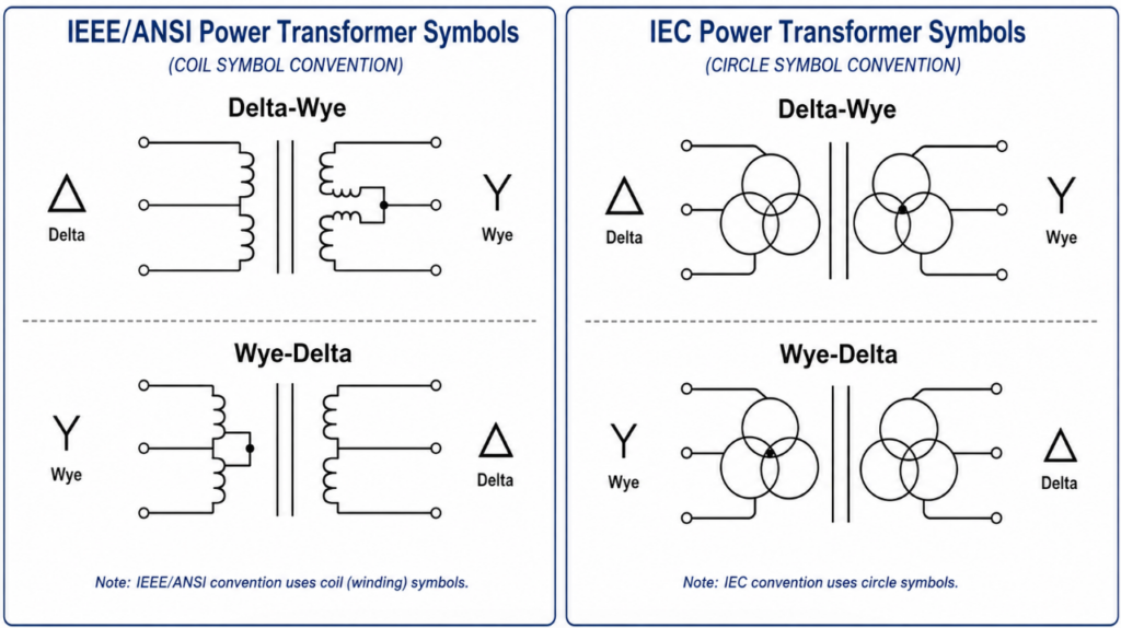
Single-Line Diagram Representation
The IEEE/ANSI power transformer symbol uses intersecting scalloped lines (representing coils), while the IEC standard uses intersecting circles. Engineers attach connection symbols directly adjacent to these icons. A triangle denotes a Delta connection; a Y-shape denotes a Wye connection.
Winding Connections in Schematics
The chosen symbol directly impacts grounding strategy. A Delta-Wye transformer symbol implies an ungrounded or high-impedance grounded source side, combined with a solidly grounded load side. Grounding the neutral of the Wye secondary provides a stable reference for phase-to-neutral loads and suppresses triplen harmonics.
Field failures in 2026 rarely stem from selecting the wrong standard MVA. They happen when static ratings collide with modern non-linear loads.
The K-Factor Trap in AI Data Centers and EV Depots
Standard power transformer ratings assume pure sinusoidal loads. EV charging banks and server racks draw heavy harmonic currents. Harmonics cause severe eddy current losses in the core and skin effect losses in the windings. A standard 1000 kVA transformer feeding an EV charging depot will burn out at 700 kVA of actual load. Facilities must specify a K-Factor rating (e.g., K-13 or K-20) which dictates a thicker winding and specialized core design to handle harmonic heating.
Dynamic Line Rating (DLR) vs. Static Nameplate
Procurement specialists waste millions by strictly adhering to the nameplate MVA limit. Modern smart grids utilize digital twins and IIoT dissolved gas analysis (DGA) sensors. These sensors monitor ambient temperature, wind speed, and real-time top-oil temperature. If ambient temperatures are 10°C below standard, the transformer can safely carry 15-20% more load than its static standard rating indicates. Utilizing DLR delays multimillion-dollar substation upgrade projects.
What is the difference between kVA and MVA in transformer ratings?
kVA (kilovolt-amperes) and MVA (megavolt-amperes) both measure apparent power capacity. 1 MVA equals 1,000 kVA. Distribution transformers are typically rated in kVA (e.g., 500 kVA), while large grid-level transformers are rated in MVA (e.g., 50 MVA).
Why do transformers have two voltage ratings?
The two ratings represent the primary (input) and secondary (output) winding voltages. A rating of 11kV / 400V means the transformer receives 11,000 volts from the grid and steps it down to 400 volts for facility utilization.
How do you read a transformer vector group symbol?
The first capital letter indicates the high-voltage winding connection (D for Delta, Y for Wye). The second lowercase letter indicates the low-voltage connection. The trailing number acts as a clock face indicating the phase shift multiplier of 30 degrees (e.g., 11 means 11 x 30 = 330 degrees or a 30-degree lead).
What does ONAN and ONAF mean on a power transformer rating plate?
These denote cooling classes. ONAN stands for Oil Natural Air Natural (passive cooling). ONAF stands for Oil Natural Air Forced (fans active). A dual rating like 15/20 MVA ONAN/ONAF means the unit handles 15 MVA passively and 20 MVA when fans turn on.
Can you run two transformers with different impedance ratings in parallel?
Operating transformers with mismatched impedance (%Z) causes unequal load sharing. The transformer with the lower impedance will draw more current and potentially overload, even if its capacity rating is identical to the parallel unit.
What is a standard power transformer impedance percentage?
Standard impedance typically ranges from 4% to 6% for transformers under 2500 kVA. Larger power transformers (above 10 MVA) generally have impedance ratings between 7% and 12% to effectively limit short-circuit fault currents.
Learn Transformer Power Calculation. Avoid Apparent Power Traps And Master The V-A-P Algorithm For Capacity Sizing.
View detailsDistribution Vs Power Transformer: 5 Core Differences. Master The L.E.N.S. Framework To Avoid Costly Sizing Traps.
View detailsPower Transformer Type Test: Learn How To Check Performance, Audit Factory Data, And Avoid Hidden Defects.
View detailsStop Power Transformer Failure: Decode Bad Symptoms And Humming Sounds. Find Hidden Causes With Our H.E.A.T. Guide.
View detailsPlease fill in the arithmetic result.
The calculation is incorrect, please fill it in again.