 BBELC
BBELC
Grounding Isolation Transformer: 5 Proven Practices
37Master Grounding Isolation Transformer Setups With 5 Proven Practices. Stop Ground Loops Using The P.A.C.T. Method.
View details
Search the whole station
Testing a power transformer requires measuring its voltage ratio to verify winding turns and executing a short circuit test to determine load losses and leakage impedance. Apply a low AC voltage to the primary winding while keeping the secondary open for the ratio test. Short the secondary terminals with heavy-duty copper buses and apply reduced voltage to the primary for the short circuit test. Field engineers frequently face discrepancies between their site data and the original factory acceptance tests (FAT). The culprit is rarely a structural failure. Uncompensated residual magnetism and incorrect temperature normalization skew the data. We will eliminate these environmental variables and establish an IEC-compliant testing baseline.
Field diagnostics demand the C.N.A. Testing Triad (Calibration, Normalization, Analysis). Precision starts with correct test lead placement and ends with mathematical correction. You must strip away contact resistance, temperature fluctuations, and stray capacitance before judging the health of the windings.
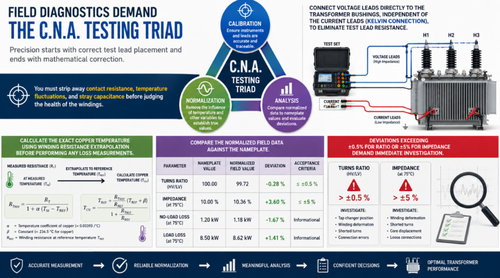
Connect voltage leads directly to the transformer bushings, independent of the current leads (Kelvin connection), to eliminate test lead resistance. Calculate the exact copper temperature using winding resistance extrapolation before performing any loss measurements. Compare the normalized field data against the nameplate. Deviations exceeding ±0.5% for ratio or ±5% for impedance demand immediate investigation.
The transformer turns ratio (TTR) test validates the fundamental relationship between primary and secondary windings. An accurate ratio test of power transformer confirms the absence of shorted turns and the integrity of the tap changer.
Step-by-Step TTR Execution
Apply a single-phase or three-phase excitation voltage to the high-voltage (HV) winding. Measure the induced voltage on the low-voltage (LV) winding simultaneously. Three-phase automated test sets handle vector group phase shifts (like the 30-degree shift in a Dyn11 transformer) internally. Test every single tap position.
“”ShiPing ChaRu”” (Prompt for editor: Insert a 60-second video demonstrating the hookup of a 3-phase TTR tester on a Dyn11 transformer here.)
Vector Group Phase Shifts & Residual Magnetism
Residual magnetism trapped in the core from previous DC tests (like winding resistance measurement) causes phantom ratio errors. The magnetic core saturates unevenly, dropping the measured voltage on the secondary side and failing the test. Run a demagnetization cycle using your test set before starting the TTR.
Contact resistance inside the On-Load Tap Changer (OLTC) creates false readings. Carbon build-up or thin oxidation layers on the diverter switch contacts add micro-ohms to the circuit, dropping the excitation voltage. Cycle the tap changer through its entire range 5 to 10 times to wipe the contacts clean before taking your official measurements.
The short circuit test of power transformer isolates the copper losses (load losses) and calculates the exact leakage reactance. This data dictates the parallel operation capabilities of the unit and its thermal rating.
Setup Requirements for Low-Voltage Excitation
Short-circuit the LV terminals using massive copper bars. The cross-sectional area of your shorting bus must equal or exceed the total cross-section of the LV winding conductors. Any resistance introduced by thin test cables or poor clamping on the shorting side will artificially inflate the load loss data. Apply a reduced AC voltage to the HV side until the rated current flows through the windings.””BiaoGe ChaRu”” (Prompt for editor: Insert a comparison table showing “Acceptable vs. Unacceptable Shorting Bus Materials and Cross-Sections” based on transformer MVA ratings.)
| Transformer Rating (MVA) | Recommended Minimum Cross-Section* | Acceptable Shorting Bus Materials | Unacceptable Materials | Additional Notes |
|---|---|---|---|---|
| ≤ 1 MVA | Equal to LV winding conductor cross-section | Solid copper bar; Laminated copper bus | Thin test leads; Small-gauge cables; Steel bars | Ensure tight clamping across all terminals |
| 1–5 MVA | Equal to or greater than LV winding conductor cross-section | Solid copper bar; Multi-layer copper bus | Flexible cables with insufficient area; Corroded copper; Steel straps | Minimize contact resistance |
| 5–20 MVA | Greater than LV winding conductor cross-section | Heavy-duty copper busbars; Laminated copper plates | Small cables; Undersized aluminum bars; Poor clamp connections | Verify full terminal contact area |
| 20–50 MVA | Exceed LV winding conductor cross-section | Large-section copper bars; Parallel copper bus assemblies | Thin jumpers; Undersized aluminum bars; Oxidized connections | Maintain mechanical rigidity |
| > 50 MVA | Determined by engineering calculation | Custom copper bus assemblies; Parallel laminated copper bars | Temporary test cables; Steel conductors; Loose bolted links | Check thermal and electrodynamic stress |
Temperature Normalization (IEC 60076 Standards)
Raw short circuit test data is useless. You must normalize the measured copper losses to a reference temperature—typically 75°C or 85°C, depending on the insulation class.
Measure the exact ambient temperature and the winding temperature immediately before the test. Use the resistance temperature coefficient formula (
R2=R1×[(T0+t2)/(T0+t1)]R2=R1×[(T0+t2)/(T0+t1)], where
T0T0is 234.5 for copper) to correct the data. Failing to correct for a 10°C difference between factory conditions and field conditions results in a 4% error in calculated load losses.
We recently evaluated a 50MVA, 132/33kV YNd11 transformer during commissioning. The initial TTR test flagged a 1.2% error on the U-phase, violating the strict ±0.5% IEC tolerance limit.
The site contractor suspected a shorted turn from transport vibration. We applied the C.N.A. framework. The pre-test checklist revealed a DC winding resistance test occurred two hours prior. The core held severe residual magnetism. We injected a decreasing alternating DC current to demagnetize the core. The subsequent TTR test yielded a maximum deviation of 0.08%, well within factory specs. This prevents unnecessary internal inspections and saves weeks of project delays.
Why do we perform the short circuit test on the high voltage side?
Applying rated current to the high voltage (HV) side requires significantly lower current from the test power supply compared to the low voltage (LV) side. Testing from the HV side keeps the test equipment smaller, safer, and more manageable in the field.
What is the acceptable tolerance for a transformer ratio test?
IEC 60076 and IEEE C57.12.90 standards mandate a maximum deviation of ±0.5% from the calculated nameplate voltage ratio. Deviations beyond this limit indicate tap changer issues or turn-to-turn faults.
How does residual magnetism affect a power transformer test?
Residual magnetism biases the core flux. When low AC voltage is applied during a ratio test, the core saturates prematurely in one direction. This distorts the induced voltage waveform, causing accurate modern digital testers to read an incorrect turns ratio.
Can you do a short circuit test at less than rated current?
Yes. Field engineers perform the short circuit test at reduced currents (typically 50% or even lower) when power supplies are limited. They square the ratio of the rated current to the test current to scale the measured load losses up to 100% rated conditions.
What causes an On-Load Tap Changer (OLTC) to fail a TTR test?
Oxidation, coked oil, or carbon buildup on the physical selector contacts increases localized resistance. This drops the voltage across the junction during the test, registering as a failed turns ratio on that specific tap.
How do you remove residual magnetism before testing a power transformer?
Apply a decreasing alternating DC voltage across the high voltage windings. Modern test sets automate this by cycling current in opposite polarities, reducing the amplitude by 10% each cycle until the core flux returns to near zero.
Master Grounding Isolation Transformer Setups With 5 Proven Practices. Stop Ground Loops Using The P.A.C.T. Method.
View detailsDiscover How Isolation Transformers Work. Learn The Definition, 5 Critical Functions, And Buyer Pitfalls.
View detailsAdvanced Power Transformer Protection Schemes To Prevent Failure. Master 87T Relays And IEC 61850 Systems Today.
View detailsMaster The Exact Electrical Symbol For Galvanic Isolation Using Transformer To Stop High Frequency Layout Failures
View detailsPlease fill in the arithmetic result.
The calculation is incorrect, please fill it in again.