 BBELC
BBELC
Full Load Power Factor & Transformer Efficiency 2026 Hacks
38Optimize Power Factor Of Transformer At Full Load. Master 2026 Hacks For Max Power Transformer Efficiency.
View detailsSearch the whole station
The primary difference between distribution and power transformer configurations lies in their load handling design and network placement. Power transformers operate at transmission networks (>33kV) under constant, near-100% load conditions, prioritizing minimal copper losses. Distribution transformers step down voltage (<33kV) for end-user facilities, operating under highly fluctuating loads (typically 50-70%), making core loss (iron loss) reduction their primary engineering focus.
Choosing the wrong specification goes beyond a simple upfront capital expenditure error. Installing a unit with mismatched load profiles forces your facility to absorb thousands of dollars in unoptimized no-load losses annually. Let’s break down the exact engineering specifications, performance data, and economic frameworks you need to specify the right equipment for your substation.
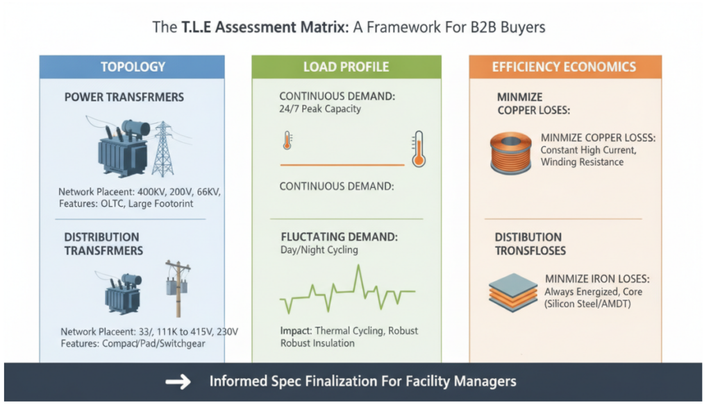
Engineering teams must evaluate transformers based on three specific pillars rather than relying on generic capacity tags. The T.L.E. Matrix (Topology, Load Profile, Efficiency Economics) provides a definitive standard for facility managers to finalize specs.
Network placement dictates the required insulation levels and structural footprint. Power transformers connect transmission grids (e.g., 400kV, 200kV, 66kV) to sub-transmission networks. Their high-voltage exposure requires massive bushings, advanced tap changers (often On-Load Tap Changers – OLTC), and substantial physical clearance. Distribution transformers sit at the terminal end of the grid, stepping down 33kV or 11kV to utility levels like 415V or 230V. Their compact topology allows for pole-mounting, pad-mounting, or integration into tight indoor switchgear rooms.
A transformer’s internal thermal design responds directly to the facility’s daily load curve. Power transformers face a continuous load profile. They run at maximum capacity 24 hours a day, meaning their internal temperature remains relatively stable at peak operating parameters. Distribution transformers face severe load fluctuations. A manufacturing plant might draw 80% capacity during the day shift and drop to 15% overnight. This constant thermal cycling demands robust winding insulation capable of handling continuous expansion and contraction without degrading.
Design engineers allocate material budgets differently based on expected loss types. Power transformers are built to minimize copper losses. Since they operate at peak current constantly, reducing the resistance in the copper windings yields the highest efficiency gains. Distribution transformers are engineered to minimize iron losses (core losses). Because they remain energized 24/7 even when plant demand drops to zero, the core continuously consumes energy to maintain the magnetic field. High-grade silicon steel or Amorphous Metal Cores (AMDT) are specified here to stop this constant energy bleed.
Comparing raw data reveals the strict operational boundaries of each transformer type. B2B buyers must align these parameters with their specific plant single-line diagrams.
MVA ratings clearly separate transmission equipment from terminal equipment. Power transformers start at 5 MVA and scale up to 500 MVA or more, handling voltages well above 33kV. Distribution transformers occupy the lower spectrum, typically ranging from 16 kVA up to 2.5 MVA (2500 kVA), operating below the 33kV threshold. When an industrial facility requires more than 2.5 MVA, engineers split the load across multiple distribution units rather than installing a single massive power transformer, ensuring redundancy and localized fault isolation.
| Parameters | Power Transformer | Distribution Transformer |
| Capacity Range | 5 MVA to 500 MVA or more | 16 kVA up to 2.5 MVA (2500 kVA) |
| Voltage Level | Above 33kV | Below 33kV |
| Flux Density | Higher flux density (operates near maximum limit) | Lower flux density (designed to strictly minimize no-load core losses) |
| Max Efficiency Point | At or near 100% full load | Around 50% to 70% of full load |
| Typical Connections | Star-Delta, Delta-Star, or Star-Star (varies by transmission network needs) | Delta Primary / Star Secondary (to provide a neutral wire for consumers) |
Thermal management dictates the physical dimensions and maintenance schedules of the unit. Distribution transformers rely primarily on ONAN (Oil Natural Air Natural) or cast-resin dry-type cooling. Their lower heat generation requires minimal auxiliary equipment, keeping the footprint compact. Power transformers mandate aggressive thermal management, utilizing ONAF (Oil Natural Air Forced), OFAF (Oil Forced Air Forced), or water-cooling systems. These active cooling banks, complete with radiator fans and oil pumps, drastically increase the installation footprint and require strict monthly acoustic and vibration monitoring.
Facility managers consistently lose money by over-specifying distribution transformer capacity. Plant engineers often calculate maximum possible peak demand, add a 30% safety margin, and purchase a vastly oversized unit.
An oversized distribution transformer operates at a very low average load factor (e.g., 25-30%). Efficiency drops drastically at low loads because iron losses remain constant regardless of the current drawn. You pay for the magnetic field 8,760 hours a year. A 2000kVA transformer running at 30% load will consume significantly more wasted energy over a 20-year lifespan than a properly sized 1250kVA unit running at its optimal 60-70% efficiency sweet spot. Match the capacity tightly to the actual load duration curve, not just the theoretical absolute peak.
Field data from a recent industrial facility upgrade proves the financial impact of exact spec matching. A polymer manufacturing plant replaced a failing 2000kVA conventional power-style transformer (running at 40% load) with two separate 1000kVA high-efficiency AMDT distribution transformers.
Q: Can a distribution transformer be used as a power transformer?
No. Distribution transformers lack the high-voltage insulation and thermal dissipation infrastructure required to handle continuous transmission-level voltages and 100% constant loads. They would overheat and suffer rapid dielectric failure
Q: At what load percentage does a power transformer achieve maximum efficiency?
Power transformers hit maximum efficiency at or very near 100% of their full load capacity. They are designed so that at full load, copper losses equal iron losses.
Q: At what load percentage does a distribution transformer achieve maximum efficiency?
Distribution transformers reach peak efficiency between 50% and 70% of full load. Engineers design them this way because typical commercial and industrial facilities rarely draw 100% continuous power.
Q: Why do distribution transformers use delta-star (Dyn11) connections?
The delta primary isolates utility-side faults, while the star (wye) secondary provides a neutral point. This neutral allows the transformer to supply both three-phase power for industrial motors (415V) and single-phase power for lighting and office equipment (230V) simultaneously.
Q: What is the lifespan difference between distribution and power transformers?
Both types are engineered for a 25 to 30-year lifespan under normal operating conditions. However, distribution transformers face higher risks of premature failure due to external factors like lightning strikes, severe load fluctuations, and unbalanced loads across phases.
Q: Should I choose an oil-filled or dry-type distribution transformer for indoor use?
Indoor installations strictly require dry-type (cast resin) distribution transformers. Oil-filled units pose unacceptable fire and explosion risks in enclosed spaces without heavy-duty fire suppression vaults. Dry-type units eliminate oil leaks and reduce fire insurance premiums for facility owners.
Optimize Power Factor Of Transformer At Full Load. Master 2026 Hacks For Max Power Transformer Efficiency.
View detailsMaster Grounding Isolation Transformer Setups With 5 Proven Practices. Stop Ground Loops Using The P.A.C.T. Method.
View detailsMaster The 2026 Power Transformer Testing Procedure And Commissioning Tests Framework To Prevent Fatal Field Traps.
View detailsDiscover How An Isolation Transformer Prevents Macroshock By Isolating Shore Ground In Marine Systems.
View detailsPlease fill in the arithmetic result.
The calculation is incorrect, please fill it in again.