 BBELC
BBELC
How Isolation Transformers Prevent Macroshock Vs GFCI
18Discover How Isolation Transformers Prevent Macroshock Vs GFCI. Compare Power Continuity And Medical Device Safety.
View detailsSearch the whole station
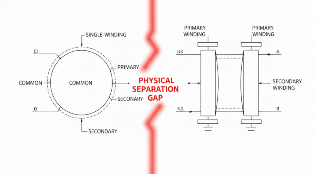
The fundamental difference between autotransformer and isolation transformer lies entirely in galvanic isolation. Autotransformers rely on a single continuous winding to step voltage up or down, offering zero electrical separation between the input source and the output load. Isolation transformers utilize physically separated primary and secondary windings, decoupling the load from the main power grid and blocking direct current (DC) and common-mode noise.
Choosing the wrong transformer does not just affect efficiency—it dictates whether your Device Under Test (DUT) survives. Connecting a grounded oscilloscope to a live circuit via an autotransformer guarantees an immediate dead short, often vaporizing the test probe and damaging the bench equipment. We will detail exactly how to select the right unit based on actual bench-test physics and cost constraints.
The V-S-C Selection Pyramid: An Engineer’s Decision Framework
Engineers need a systematic method to choose between these two technologies. The V-S-C Selection Pyramid reduces this engineering problem to three rigid steps.
Base Level: Voltage Ratio Dynamics (V)
Voltage transformation ratios dictate the physical viability of an autotransformer. When the required step-up or step-down ratio is close to 1:1 (for example, 220V to 110V), an autotransformer requires significantly less copper and core material. A closely matched ratio maximizes the shared winding portion, driving electrical efficiency above 98%. When the ratio exceeds 3:1, the size and cost advantages of the autotransformer diminish rapidly.
Middle Level: Galvanic Isolation Requirements (S)
Safety specifications veto cost savings. If the downstream hardware interacts with human operators or sensitive measuring equipment, galvanic isolation becomes a non-negotiable requirement. Isolation transformers break the electrical connection to the earth ground of the utility supply. This physical gap prevents current from finding a return path through the operator or the test chassis.
Apex Level: Cost and Footprint (C)
Industrial control panels prioritize space. Autotransformers dominate high-density motor control applications because they weigh up to 50% less and occupy a fraction of the cabinet space compared to a dual-winding unit of the same kVA rating.
| Transformer Type | Galvanic Isolation | Copper Weight | Voltage Ratio Efficiency | Typical R&D Use Case |
| Autotransformer | No (Primary and secondary share a common winding, meaning no electrical separation) | Lighter(Requires less copper since windings are shared; significantly smaller for ratios close to 1:1) | Extremely High (Only a portion of the power is transferred magnetically; highly efficient for small voltage steps) | Variable Voltage Supply (e.g., Variacs for testing equipment at varied line voltages, brownout testing) |
| Isolation Transformer | Yes(Primary and secondary windings are physically and electrically separated) | Heavier (Requires full, separate copper windings for both primary and secondary sides) | Standard/High (Lower efficiency compared to autotransformers, as 100% of power must be transferred magnetically) | Safety & Noise Isolation(Protecting users during live circuit probing, eliminating ground loops, safe oscilloscope measurements) |
The Ground Loop Trap: Why Oscilloscopes Blow Up Without Isolation
Bench testing switch-mode power supplies (SMPS) introduces severe risks that textbook definitions ignore. Many novice R&D personnel fail to understand the core difference auto transformer and isolation transformer architectures when setting up their diagnostic gear.
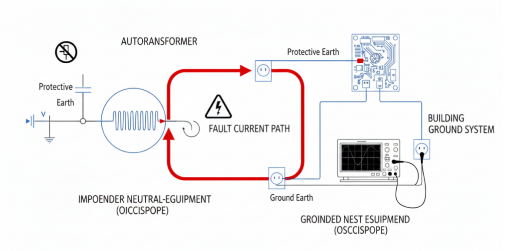
Standard oscilloscopes have their BNC probe ground clips tied directly to the earth ground of the facility’s mains power. When you use a variable autotransformer (Variac) to power a DUT, the circuit remains directly referenced to the utility line. Clipping the oscilloscope ground to the primary side of the hot DUT creates a direct short circuit through the probe, straight to the earth ground.
Isolation transformers eliminate this catastrophic path. By utilizing an isolation transformer to power the DUT, the circuit becomes “floating.” The test equipment can now safely reference any point in the circuit without creating a deadly ground loop.
Bench Test Data: Managing Common-Mode Noise in High-Frequency Loads
Modern power electronics rely heavily on Silicon Carbide (SiC) and Gallium Nitride (GaN) transistors. These components switch at extreme frequencies, generating intense common-mode noise.
In a recent Q4 2023 lab benchmark involving a 5kW SiC EV motor drive, engineers tested both transformer types to measure harmonic mitigation.
The physical separation in the isolation transformer blocks high-frequency noise that easily travels across the shared winding of an autotransformer. For compliance testing against EMI/EMC standards, isolation transformers provide the necessary clean power baseline.
Autotransformer Industrial Applications: Efficiency Over Separation
Industrial infrastructure scales differently than R&D labs. Factory floor engineers install autotransformers for massive induction motors and long-distance voltage drop compensation.
Starting large AC motors requires stepping down the voltage temporarily to reduce massive inrush currents. Autotransformers execute this flawlessly via reduced-voltage starters. Since the entire industrial grid is already heavily grounded and isolated at the main substation, paying a premium for localized galvanic isolation at every motor is a massive waste of capital. Autotransformers deliver the required voltage drops with minimal copper loss and thermal output.
FAQ
Q1: Can I use an autotransformer to fix a ground loop?
No. Autotransformers share a common winding and maintain the original ground reference. You must use an isolation transformer to break the electrical connection and resolve ground loop issues.
Q2: Why is an autotransformer smaller than an isolation transformer?
An autotransformer utilizes a single winding acting as both primary and secondary. This shared physical infrastructure means it requires significantly less copper wire and a smaller magnetic iron core to achieve the same power (kVA) rating.
Q3: Does the difference between autotransformer and isolation transformer affect power consumption?
Yes. Autotransformers generally exhibit higher electrical efficiency and lower voltage drops (impedance) because a portion of the power transfers directly through electrical conduction rather than purely through magnetic induction.
Q4: Is a variable transformer (Variac) an autotransformer or isolation transformer?
Standard Variacs are strictly variable autotransformers. They do not provide mains isolation. If you need adjustable isolated voltage, you must wire an isolation transformer in series with the Variac.
Q5: When should I definitely avoid using an autotransformer?
Avoid autotransformers when working with medical equipment, performing live diagnostics with grounded test gear, or operating in wet environments. In these scenarios, the lack of galvanic isolation presents an unacceptable electrocution risk.
Discover How Isolation Transformers Prevent Macroshock Vs GFCI. Compare Power Continuity And Medical Device Safety.
View detailsFind A Pad-Mounted Distribution Transformers Factory. Secure DOE 2016 And IEEE Units In 20 Weeks. Bypass Fake OEMs.
View detailsDiscover The Difference Between Power And Distribution Transformer. Master 2026 Specs, DOE Rules And The 3-T Matrix.
View detailsAre Large Power Transformers Custom Made? Get Exact 2026 Power Transformer Pricing, Hidden Costs, And Hard Market Data.
View detailsPlease fill in the arithmetic result.
The calculation is incorrect, please fill it in again.