 BBELC
BBELC
Large Power Transformer Efficiency Losses Percentage Data
39Large Power Transformer Efficiency Losses Percentage Data: Audit Grid Harmonics And Optimize Asset Opex.
View details
Search the whole station
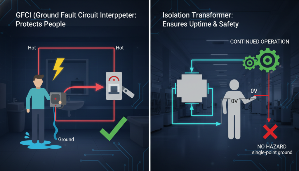
Isolation transformers prevent macroshock by completely removing the earth ground return path, requiring two simultaneous independent faults for a shock to occur, while keeping electrical equipment fully operational. GFCIs prevent shock by instantly cutting off power when they detect a current imbalance as low as 5mA.
For a homeowner, a GFCI shutting off a hairdryer saves a life. For a medical device engineer designing an operating room setup, a GFCI shutting off a ventilator or heart-bypass machine kills the patient.
Understanding the precise mechanical differences between gfci vs isolation transformer determines whether a safety system protects lives or inadvertently ends them through power loss. The engineering choice comes down to one metric: tolerance for power interruption. Let’s examine exactly how does isolation transformer prevent macroshock without sacrificing power continuity, and why relying on basic residential GFCI logic fails in high-risk industrial and medical environments.
H2: The C.I.E. Defense Model: Diagnosing Macroshock Prevention
Engineers must frame shock protection through the C.I.E. Defense Model (Cutoff, Isolation, Elimination). Different environments demand different tiers of this model.
H3: GFCI (Cutoff Tier): Protection via Instant Interruption
GFCIs operate entirely on the principle of acceptable thresholds. A standard GFCI monitors the current difference between the hot and neutral wires. A discrepancy of 4 to 6 milliamperes triggers the internal relay, opening the circuit in roughly 25 milliseconds.
The immediate cessation of current flow prevents the macroshock from reaching lethal ventricular fibrillation levels. The system accepts total power failure as the cost of safety. Wet environments like bathrooms or outdoor construction sites mandate this approach because the risk of a primary ground fault is exceptionally high.
H3: Isolation Transformers (Isolation Tier): Protection via Earth-Decoupling
Isolation transformers operate on the principle of galvanic isolation. They transfer alternating current from the source to the device using magnetic induction across an air gap, with no physical wire connection.
The secondary winding of a true isolation transformer does not connect to earth ground. A person touching a single live wire on the secondary side completes no circuit because the electricity has no pathway back to the source via the earth. This design guarantees power continuity during a single fault condition.
H2: How Does an Isolation Transformer Prevent Macroshock?
Macroshock occurs when a large current passes through the body, typically externally through the skin, moving toward the earth. Isolation transformers dismantle this mechanism at the physics level.
H3: Eliminating the Ground Return Path
Utility power grids tie their neutral lines to the earth. Standing on the floor makes you a conductor back to that utility source.
An isolation transformer creates a localized, self-contained floating power grid. The electricity flowing from its secondary winding only wants to return to the opposite end of that specific secondary winding. It has no relationship with the earth. If an engineer touches an exposed conductor powered by an isolation transformer while standing on a concrete floor, no current flows through them. The electrons have no physical reason to travel to the ground.
H3: The Double-Fault Requirement for Electrocution
Standard electrical systems require only one fault (touching a live wire) to cause a macroshock. Isolation transformers demand two simultaneous faults to create a hazard.
For a macroshock to occur on an isolated circuit, Fault A must connect one side of the secondary winding to the earth, and Fault B must involve a person touching the other side of the secondary winding while grounded. Statistical probability makes simultaneous double faults exceptionally rare, which satisfies strict IEC 60601-1 safety margins for critical care environments.
H2: GFCI vs Isolation Transformer: Engineering Decision Matrix
Specifying the wrong protection device causes immediate compliance failures or operational disasters. We analyzed failure modes across both technologies to establish concrete deployment rules.
H3: The “Nuisance Trip” Hazard in Life-Support Systems
GFCIs fail catastrophically in environments with high cumulative leakage currents. Operating rooms contain dozens of electronic devices. Each device naturally leaks a tiny amount of current (often 0.5mA to 1mA) due to internal EMI filters and parasitic capacitance.
Ten devices plugged into a single GFCI-protected circuit will generate enough combined baseline leakage to trip the breaker. This “nuisance tripping” shuts down life-support equipment during surgery. Hospital IT networks (Isolated Power Systems) use isolation transformers combined with Line Isolation Monitors (LIM) precisely to avoid this. The LIM sounds a visual/audio alarm when the first ground fault occurs, alerting staff, but keeps the equipment running. Surgery continues. Maintenance resolves the fault later.
| Application Scenario | Preferred Technology | Fault Tolerance (Single/Multiple Faults) | Power Outage Consequence Score (1-5, 5=Severe) | IEC/NEC Standard Requirements |
| Operating Room | Isolation Transformer | Multiple (critical) | 5 | IEC 60364-7-710 (Medical locations) |
| Home Bathroom | GFCI (Ground Fault Circuit Interrupter) | Single (life safety) | 3 | NEC 210.8(A)(1) (Dwelling Units – Bathrooms) |
| Heavy Industry Test Bench | Isolation Transformer (IT system) | Multiple (safety & uptime) | 4 | IEC 60364-4-41 (Protection against electric shock) & local industrial codes |
H3: Leakage Current Limits and Compliance
GFCIs ignore microshock risks. A 4mA current passing directly through a catheter into a patient’s heart is lethal, yet a GFCI will not trip because it remains below the 5mA threshold.
Medical-grade isolation transformers address both macroshock and microshock. By strictly limiting patient leakage current to under 100 microamps (µA) for Type BF applied parts, they provide a safety resolution that GFCIs simply cannot process.
H2: Insider Pitfall: The Capacitive Coupling Trap in Non-Medical Transformers
Many engineers purchase standard industrial isolation transformers expecting total macroshock and microshock immunity. They ignore capacitive coupling.
Standard transformers wind the primary and secondary coils closely together. High-frequency noise and AC voltage create a parasitic capacitor across the air gap between these windings. This capacitance provides a hidden pathway for AC leakage current to cross the isolation barrier and enter the medical device chassis.
You must specify isolation transformers built with a grounded Faraday Shield between the primary and secondary windings. This thin copper shield intercepts the capacitive leakage current and shunts it safely to the earth ground before it reaches the secondary circuit. Without a Faraday Shield, your “isolated” system will fail rigorous leakage testing.
1. Can I use a GFCI and an isolation transformer together?
Yes, but placement matters. Placing a GFCI on the primary (input) side of an isolation transformer protects the wiring leading up to the transformer. Placing a GFCI on the secondary (isolated) side is usually ineffective because the isolated circuit has no earth reference for the GFCI to measure a ground fault against.
2. Does an isolation transformer protect against line-to-line shocks?
No. If you touch both the active and neutral wires on the secondary side of an isolation transformer simultaneously, your body becomes the load. Current will flow directly through you from one wire to the other. Isolation transformers only protect against line-to-ground macroshocks.
3. Why do hospitals use isolation transformers instead of GFCIs in operating rooms?
Hospitals use them to ensure power continuity. A GFCI cuts power immediately upon detecting a fault, which is deadly if the device is a ventilator. An isolation transformer prevents the shock but keeps the power running during a single ground fault, allowing the surgical team to finish the procedure safely.
4. What is the difference between microshock and macroshock?
Macroshock occurs when a large current (typically >10mA) passes through intact skin and the body. Microshock involves very small currents (as low as 10µA) applied directly to the heart tissue via internal catheters or pacemakers. Isolation transformers with low capacitive leakage are required to prevent microshock.
5. How do you test if an isolation transformer is working correctly?
Engineers test isolation transformers using an electrical safety analyzer to measure the dielectric withstand voltage (Hipot testing) and the earth leakage current across the primary to secondary barrier. The resistance between the secondary winding and earth ground should read as infinite under normal conditions.
6. Do standard power strips have isolation transformers?
No. Standard power strips only contain surge protectors (MOVs) to block voltage spikes. They do not contain isolation transformers and provide zero protection against macroshocks or ground loop faults. True isolation transformers are heavy, copper-wound devices.
Large Power Transformer Efficiency Losses Percentage Data: Audit Grid Harmonics And Optimize Asset Opex.
View detailsMaster Power Transformer Inspection, Maintenance And Testing SOP To Detect Internal Arcing And Prevent Grid Failures.
View detailsStop 2026 Utility Fines From No-Load Transformer Power Factor. Prevent Off-Peak Energy Loss With Our MAP Framework.
View detailsThe fundamental difference between autotransformer and isolation transformer lies entirely in galvanic isolation. Autotransformers rely on a single continuous winding to step voltage up or down, offering zero electrical separation betwe...
View detailsPlease fill in the arithmetic result.
The calculation is incorrect, please fill it in again.