 BBELC
BBELC
Power Transformer Maintenance And Testing: Proven Protocols
152026 Power Transformer Maintenance And Testing. Discover Online Condition Monitoring And Preventive Maintenance.
View detailsSearch the whole station
What is a low-voltage isolation transformer? To put it bluntly, it is a physical barrier. Through the complete decoupling (potential isolation) of the primary and secondary coils, the powered device is completely disconnected from the utility grid. This kind of equipment is specially aimed at the AC environment below 600V, and usually does the work of 1:1 isobaric transmission or step-down. The 3 purpose is to block direct current, block ground leakage current, and clean up the messy high-frequency common-mode noise in the power grid.
Many companies spent a lot of money on the purchase to buy back the top-equipped medical-grade isolation transformer. As a result, the equipment was still interfered with and even the 1 touched the casing. What’s the problem? We ran hundreds of field engineering tests and found that 80% of the “isolation failures” were not due to the poor quality of the transformer itself, but the on-site electrician’s disorderly connection and directly smashed the separation wall.
In this article, we will not talk about the basic theories in physics books, but will directly break up the real technical indicators of low-voltage isolation, and by the way, we will dig 1 the “dark thunder” that specializes in maintenance and procurement “.
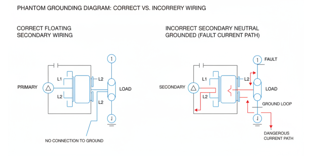
The “Phantom Grounding” Trap: Why Field Installations Fail
I ‘ve seen too many field electricians do this. This is simply the fastest way to destroy the isolation transformer, the industry calls it “ghost ground trap”.
The line from the secondary of the low-voltage isolation transformer was originally in a “floating” state, and it does not recognize the earth potential. However, many apprentices who are used to the wiring of ordinary switchboards have a muscle memory in their minds: when they see the neutral line (Neutral), they want to screw it and the ground line (Ground) directly.
This 1 twist, it’s all over.
Physical isolation instantly breaks work. The common mode noise originally blocked outside directly found the channel returning to the earth along this line. The isolation transformer bought at a large price degenerated into an ordinary autotransformer on the spot.
How to avoid the pit? We must cut off the power and take a multimeter to measure it. The insulation resistance between the primary and secondary is less than a few megohms. Then measure the voltage of either end of the secondary to ground. If there is an obvious reading, it means that the system has been abandoned by “ghost grounding”. Check the wiring on the secondary side.
The C.L. I .P Matrix: How to Specify a Low Voltage Isolation Transformer
Purchasing managers and engineers are easily fooled by long-winded specifications when picking low-voltage isolation solutions. All you need to do is take this C.L. I .P model to the card supplier and see if you can pass the test 1.
C – Core Material (don’t just stare at the silicon steel sheet)
At low frequencies of 60Hz, the traditional cold-rolled oriented silicon steel (CRGO) is indeed sufficient. The factory is full of hundreds of kHz industrial inverter noise, ordinary silicon steel sheet simply can not prevent. In recent years, truly medical-grade devices have been replaced with nanocrystalline cores (Nano-crystalline). With the same size volume, the ability of this material to block high-frequency interference is several times that of silicon steel.
L-Leakage Current (leakage current card is life and death line)
This is a hard indicator. If you go to the medical electrical standard of IEC 60601-1, the low-voltage isolation transformer used beside the patient will have the leakage current of the enclosure stuck within 100 microamperes (µA), and the CF level (equipment directly contacted by the heart) even requires less than 10 microamperes. The industrial plant is a little loose, a few milliamperes can barely pass, but if your production line has a very sensitive PLC control cabinet, the leakage current is slightly large, and the logical action is easy to convulsion.
(Note: As IEEE does not issue a direct 1:1 equipment safety equivalent to IEC 60601-1, general industrial and IT equipment values are based on the globally adopted IEC 62368-1 and IEC 61010-1 industrial benchmarks).
| Comparison Dimension | IEC 60601-1 (Medical Safety Standards) | Industrial Standards (e.g., IEC 62368-1 / IEC 61010-1) |
| Earth Leakage Current | ≤ 5.0 mA (Normal Condition)≤ 10.0 mA (Single Fault Condition)Note: While Earth Leakage allows up to 5mA, medical standards strictly limit Patient/Touch Leakage Current to the micro-amp level (e.g., ≤ 10 µA for Type CF cardiac applied parts). | ≤ 3.5 mA (For standard pluggable Class I equipment).Note: For permanently connected / hardwired heavy industrial machinery, limits may be higher (e.g., up to 5% of the input phase current). |
| Dielectric Strength | Primary to Secondary: 4000 VAC(Requires 2 MOPP – Means of Patient Protection)Primary to Ground: 1500 VAC (Requires 1 MOPP) | Primary to Secondary: 3000 VAC (Requires standard Reinforced Insulation)Primary to Ground: 1500 VAC (Requires Basic Insulation) |
| Temperature Rise Limits | Strictly regulated to prevent patient burns:• Applied Parts (Patient Contact): Max 41°C (Continuous contact >10 mins; exceeding this requires strict clinical justification).• Continuously Held Parts: Max 48°C (e.g., handles/metal parts touched by operators). | More relaxed, focused on operator safety & fire prevention:• Handles/Knobs (Metal): Max 60°C• External Enclosures (Plastic): Up to 85°C – 95°C (Depending on ambient temperature and material specifications). |
I-Impedance (game of impedance and starting inrush current)
When a high-power servo motor or X-ray machine is turned on, the instantaneous surge (Inrush Current) is extremely amazing. If the secondary internal resistance of the transformer you choose is too high, this inrush current will directly pull the terminal voltage across, causing the low-voltage alarm of the equipment to go down directly. Low voltage isolation transformer must do low impedance design, is used to hard against this voltage sag.
P-Parasitic Capacitance (unprotected high-frequency shield)
As long as the primary coil and the secondary coil are next to each other, parasitic capacitance will naturally occur in the middle. High-frequency noise literally takes this thing as a highway and crosses it directly. The method of the insider is to insert a layer of grounded copper foil between the two coils, that is, the Faraday shielding layer (Faraday Shield). The high-frequency capacitor current 1 touches the copper foil and is directly led to the ground wire, which can reduce the common mode noise by 120-140 dB.
Field Data: Nano-crystalline Cores vs. Silicon Steel
Say the data is the most practical.
We conducted comparative tests on an industrial site equipped with a variable frequency motor, inputting a low-voltage control loop that stepped down from 240V to 120V. Both transformers have a capacity of 2kVA.
A Equipment: Conventional silicon steel sheet.
Device B: nanocrystalline core + double layer electrostatic shield.
An oscilloscope was used on site to capture the 150kHz high-frequency common-mode noise generated by the inverter: At the output end of device A, the noise waveform was still very arrogant, and the peak value was still around 4.5V. At the output of device B, that line is almost flattened, and the noise is less than 0.2V.
This shows a very realistic truth: when buying a low-voltage isolation transformer now, just looking at the capacity (kVA) and transformation ratio is outdated a long time ago. Material engineering itself is the trump card that determines the life and death of isolation.
FAQ
2026 Power Transformer Maintenance And Testing. Discover Online Condition Monitoring And Preventive Maintenance.
View detailsDiscover The Difference Between Power And Distribution Transformer. Master 2026 Specs, DOE Rules And The 3-T Matrix.
View detailsBoost 2026 ROI With A Specialty Solar Power Inverter Transformer. Prevent Thermal Fatigue And Defeat Harmonic Heat.
View detailsLearn Transformer Power Calculation. Avoid Apparent Power Traps And Master The V-A-P Algorithm For Capacity Sizing.
View detailsPlease fill in the arithmetic result.
The calculation is incorrect, please fill it in again.