 BBELC
BBELC
Transformer Idle Consumption: Does It Always Draw Power?
7Does A Transformer Always Draw Power? Learn How Much Power Does A Transformer Consume When Idle And Avoid Energy Loss.
View detailsSearch the whole station
The exact formula for calculating transformer power is very simple:
kVA = (volts x amperes)/1000 for single-phase systems and kVA = (volts x amperes x 1.732) / 1000
for three-phase systems. It’s just pure mathematical theory. The real disaster often occurs when young electricians connect 100 kW induction motors directly to 100 kVA transformers. The equipment will directly trip or even burn out due to overheating. Reactive power and low power factor will drain your equipment capacity in advance before the load reaches the nameplate rating. Next, I will disassemble how to accurately evaluate the apparent power of a transformer and use a field-proven framework to help you avoid low-level errors that can destroy the entire distribution room.
The formula determines the capacity floor of the distribution system. You need to apply specific formulas based on the phase configuration on site to arrive at the most basic transformer capacity requirements.
calculation of single phase transformer:
Appreciated power (kVA) = (voltage x current)/1000.
The bottom line for a single-phase device that draws 100 amps at 240V is a 24 kVA transformer.
calculation of three phase transformer:
The apparent power (kVA) = (voltage x current x 1.732)/1000.
Don’t forget to multiply by the root number three (1.732). If a 480V three-phase system runs at 100 amps, you must have an 83 kVA transformer.
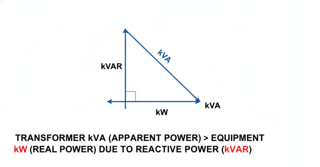
The apparent power trap: Why kVA never equals kW
The nameplate of the equipment is marked with “active power” (kW) for performing work, but the output of the transformer is the total “apparent power” (kVA). Equal sign of these two data is the most common cause of transformer thermal collapse. Active power (kW) is responsible for doing dirty work, such as turning the pump spindle. The apparent power (kVA) is the total energy that the entire system must provide, which includes the reactive power (kVAR) used to maintain the operation of the electromagnetic field.
Deadly “Nameplate Blind”
Superstitious about the kW value on the motor nameplate and not counting the power factor (PF), primary electricians often burn the primary side fuse. A standard industrial induction motor, the power factor is usually only about 0.80. If your motor requires 80 kW of mechanical power, it will actually draw 100 kVA of apparent power from the transformer (0.80=100). Connect the 80 kW load directly to the 80 kVA transformer, and you will create a serious overload of 20% at the moment of startup.
Harmonic interference caused by frequency converter and charging pile
Modern non-linear loads can severely distort the current waveform, resulting in deadly high temperatures inside the transformer core. Frequency converter (VFD), LED drive power supply and electric vehicle (EV) charging pile will pour a large amount of harmonic current into the power grid. These non-linear loads force the transformer to withstand high-frequency clutter, and these clutter will not show up on ordinary kW meters. In view of this poor heat dissipation demand, you must choose K factor (K-rated) transformer. Using the simplest kVA mathematical formula to match 1 EV charging piles with ordinary transformers, the equipment will definitely not survive the first month after startup.
V-A-P 3 step measurement algorithm: transformer selection framework for first-line maintenance personnel
Relying on guesses will only burn the equipment to ashes. The V-A-P (voltage-current-power factor) measurement method is a hard core framework used by senior maintenance supervisors during on-site inspections to ensure that you do not miss any hidden load variables.
Step 1: Verify Voltage (V) and Phase Configuration
Rigorous alignment of the primary and secondary voltages with the on-site grid and equipment requirements is a non-negotiable first step. You must confirm whether the power supply is 208V, 240V, 480V or 600V, and find out whether the load needs single-phase or three-phase power. Taking the single-phase calculation formula to assign transformers to three-phase equipment will immediately result in a 42% capacity deficit.
Step 2: Lock Peak Current (A) and Boot Surge
The transformer should not only be able to withstand the running current, but also survive the impact of the startup surge. Large motors draw an instantaneous current of up to 6 times the full load current (FLA) in the first few seconds of starting. The transformer capacity you choose must be able to eat this surge, and at the same time ensure that the line voltage drop is not so low that the contactor is directly disconnected and tripping.
Step 3: substitute power factor (P) and NEC continuous load law
The National Electrical Code (NEC) mandates that the power supply capacity of a load that runs continuously for more than 3 hours must be configured at 125 percent of the actual power consumption. You need to take the basic kW value, divide it by the power factor to get the real kVA, and then multiply it by the 1.25 safety factor.
| Equipment Type | Load (kW) | Power Factor (PF) | Original kVA | NEC 125% Adjusted kVA |
| Water Pump (Centrifugal) | 30 | 0.85 | 35.3 | 44.1 |
| Air Compressor | 75 | 0.88 | 85.2 | 106.5 |
| Industrial Fan / Blower | 45 | 0.82 | 54.9 | 68.6 |
| Conveyor Motor | 22 | 0.80 | 27.5 | 34.4 |
| HVAC Chiller | 150 | 0.90 | 166.7 | 208.4 |
| Hoist / Crane | 55 | 0.75 | 73.3 | 91.7 |
| Hydraulic Pump | 90 | 0.86 | 104.7 | 130.8 |
| Extruder Machine | 110 | 0.85 | 129.4 | 161.8 |
Real tragedy: A transformer meltdown triggered by a $75000 chiller
Pure book theory is useless when the complex conditions of the scene are involved. Last year, a manufacturing plant replaced a 75 kW high-efficiency chiller. The factory’s maintenance monitor directly connected it to an old 100 kVA transformer. On paper, 75 is smaller than 100. But the reality is that the primary coil of the transformer completely melted in 72 hours.
Here is the fatal data extracted from the accident report:
In the summer full load condition, the actual power factor of the chiller is only 0.78.
True apparent power calculation: 75 kW / 0.78 PF = 96.1 kVA.
The chiller runs continuously for 10 hours a day. Apply NEC’s 125% continuous load rule: 96.1 kVA x 1.25=120.1 kVA.
The 100 kVA transformer has actually been running in a high fever under a 20% overload state, which eventually led to the complete collapse of the insulation layer.
The maintenance team later replaced a 150 kVA transformer to completely solve the overheating problem. If they had counted the real apparent power (apparent power) at that time, instead of staring at the kW wiring on the nameplate, this maintenance tragedy worth tens of thousands of dollars could have been avoided.
FAQ
How can I convert the kW of a transformer into kVA?
Divide the kW of the equipment directly by its power factor (PF). If you don’t know the specific value in the industrial environment, it will be calculated by 0.8 by default. For example, if you need to drive a load of 100 kW, the formula is 100 kW/0.8=125 kVA.
What is the concept of transformer’s apparent power (apparent power of transformer)?
The apparent power is the total amount of electricity that the transformer must output to the circuit, in kVA. This account includes both the active power (kW) that is actually used for work and the reactive power (kVAR) that is specifically used to create a magnetic field inside the motor but does not produce actual mechanical work.
Why are transformers marked kVA instead of kW?
Transformer manufacturers have no idea what kind of power factor equipment you want to connect to it. The heat generated inside the transformer is completely determined by the voltage and total current (I. e. apparent power), which is converted into actual mechanical work (kW) regardless of how much of these electricity is finally converted.
A 100kVA transformer, how much load can I hang at most?
The continuous load must not exceed 80% of the total capacity of the transformer. For a 100 kVA transformer, the continuous apparent power limit for safe operation is strictly 80 kVA.
The power factor of the equipment is low, will it really damage the transformer?
Absolutely it will. A very low power factor will force the transformer to deliver more current in order to make up the kW power required for work. These extra currents can produce extremely high temperatures, roasting the coil insulation and halving the life of the transformer.
What is the capacity of the three-phase transformer?
Multiplies the line voltage by the phase current, the resulting number is multiplied by 1.732 (that is, the square root of 3), and finally divided by 1000 to convert to kilovolt-amperes (kVA). The hard core calculation formula is:(V x I x 1.732)/1000.
Does A Transformer Always Draw Power? Learn How Much Power Does A Transformer Consume When Idle And Avoid Energy Loss.
View detailsInside A Power Transformer: Teardown Of Seven Core Parts, Bushings, Cooling Systems And Winding Configurations.
View detailsMaster Grounding Isolation Transformer Setups With 5 Proven Practices. Stop Ground Loops Using The P.A.C.T. Method.
View detailsAutotransformer Vs Isolation Transformer: 2026 Facts. Compare Voltage Stabilizers And Power Conditioners For B2B.
View detailsPlease fill in the arithmetic result.
The calculation is incorrect, please fill it in again.