 BBELC
BBELC
DC & Drive Isolation Transformer Specification For 2026
22Master The 2026 Drive Isolation Transformer Specification. Upgrade DC Isolation Transformers To Stop VFD Failures.
View detailsSearch the whole station
Are large transformers (more than 100 MVA) pure custom made or off-the-shelf manufacturing? The answer is: absolute customization on demand. Each grid node has unique impedances, space constraints, and cooling requirements. However, there has been a fundamental shift in the industry’s definition of “custom. At present, the delivery period of large transformers in the world is approaching 120 weeks. The next generation manufacturing mode has already abandoned the tradition of “drawing drawings from zero” and has turned to the hybrid configuration mode of “platform base + highly customized peripheral interface. Grid planners who remain crippled and insist on 100 per cent full-custom procurement are bound to face budget overruns and long supply chain delays. The following is a transformer selection and specification formulation strategy for the world’s top power grid operators to shorten the delivery time by 40% while perfectly matching the project site.
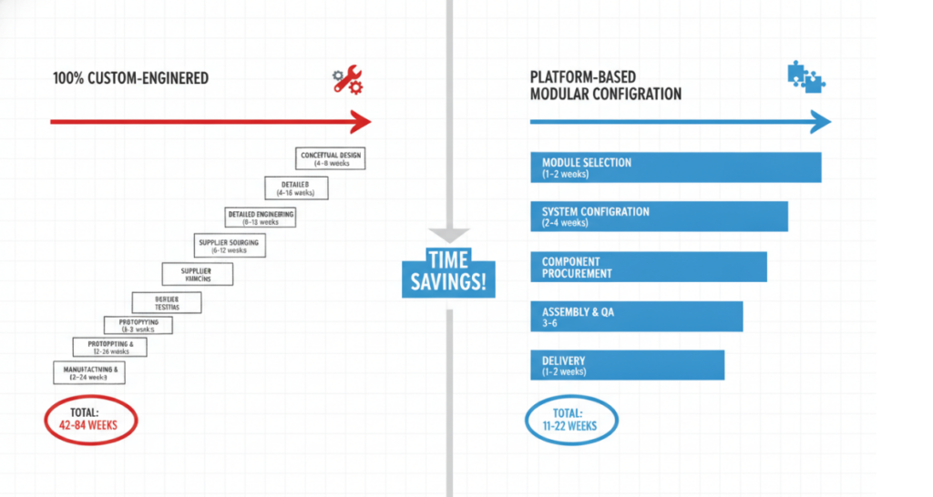
The platform-based modular design constitutes a new benchmark for current large transformer manufacturing. By standardizing the body (I. e. core and coil assembly), manufacturers transfer all site-specific customization requirements to external auxiliary equipment, such as cooler banks and control cabinets. This strategy compresses the engineering validation phase, which would have taken months, into just a few weeks.
“Customized on demand” no longer means redesigning the internal electromagnetic core. Top transformer factories pre-validate the short circuit withstand capability and thermal performance limits of the base platform design. Under this framework, customers only need to accurately configure the specific MVA capacity, on-load voltage regulating switch (OLTC) specifications and casing layout in a modular stacking manner.
Core standard parts: The step seam design and winding structure of the core must absolutely use the manufacturer’s pre-designed platform. Forcing a special internal insulation spacing or non-standard dielectric structure will force the factory to re-run a full set of thermodynamic and dielectric simulations, which will add at least 16 weeks to your delivery time.
Auxiliary configuration: On-load tap switch (OLTC), high voltage bushing and cooling system (ONAN/ONAF/OFAF) shall be directly selected from the manufacturer’s verified first-line supplier catalog (e. g. MR, Trench). The forced designation of an unpopular brand of casing in the specification can directly disrupt the manufacturer’s mature supply chain and make the final in-plant acceptance test (FAT) extremely cumbersome.
Full customization of the periphery: Physical footprint, shipping size constraints, and digital sensor integration must be absolutely customized on site. The energy of the senior engineer should be fully focused on these peripheral designs to ensure that this behemoth can be smoothly placed on the original substation base and safely pass the load-bearing limits of all bridges on the logistics route.
| Component Category | Modules that Should Be Standardized (Standard Platforms / COTS*) | Modules that Must Be Completely Customized (Application-Specific) |
| Electrical Components | • Power Supplies: Standard ATX, DIN-rail power units, or standard AC/DC adapters.<br>• Connectors & Cables: Standard USB, RJ45, standard wiring harnesses, and terminal blocks.<br>• Basic Sensors & Actuators: Standard temperature, pressure, or proximity sensors.<br>• Protection Devices: Fuses, standard circuit breakers, and relays. | • Main Control Boards (PCBs): Custom-shaped motherboards designed to fit specific form factors.<br>• Specialized Antennas: Custom RF/wireless antenna designs tuned to the specific product housing.<br>• Custom Battery Packs: Battery configurations shaped to fit specialized enclosures.<br>• Signal Conditioning: Custom circuits designed for proprietary sensor inputs. |
| Mechanical Components | • Fasteners & Hardware: Standard screws, bolts, nuts, washers, and hinges.<br>• Motion Components: Standard NEMA stepper motors, standard bearings, rails, and gears.<br>• Basic Enclosures: Standard 19-inch racks or standard NEMA-rated junction boxes.<br>• Cooling Fans: Standard off-the-shelf fans and vents. | • Outer Housings/Casings: Custom-molded plastic or machined metal shells defining the product’s industrial design.<br>• Structural Frames: Internal chassis tailored to hold the specific custom layout of components.<br>• Custom Heat Sinks: Thermal management solutions shaped to specific high-power custom PCBs.<br>• Specialized Mechanisms: Custom cams, linkages, or robotics end-effectors for unique tasks. |
| Digital / Software Components | • Core Systems: Operating systems (e.g., Linux, RTOS, Windows).<br>• Communication Protocols: Standard stacks (TCP/IP, Bluetooth, Wi-Fi, CAN bus, I2C, SPI).<br>• Foundational Libraries: Standard UI frameworks, basic hardware drivers, and database engines.<br>• Middleware: Standard third-party APIs or cloud infrastructure services (e.g., AWS/Azure basics). | • Core Business Logic: Proprietary algorithms and application-specific workflows.<br>• User Experience (UI/UX): Custom interface design, branding, and user flow tailored to the end-user.<br>• Specialized AI/ML Models: Models trained specifically on the company’s proprietary data.<br>• Security Architectures: Application-specific encryption logic, custom DRM, or proprietary data formats. |
3.1 ester insulating oil completely changes the cooling customization scheme
Replacing traditional mineral oils with natural or synthetic esters fundamentally changes the logic of customizing the cooling infrastructure. The extremely high kinematic viscosity of ester liquids completely changes the fluid dynamics inside the transformer. Manufacturers must specifically customize wider internal cooling oil passages and resize the external radiator group to compensate for the changed heat dissipation rate.
3.2 native digital twin integration
Modern large transformers require the digital twin system to be natively integrated at the factory manufacturing stage, rather than a clumsy external retrofit after installation. A truly future-oriented customized solution will directly embed the fiber temperature sensor into the hot spots of the winding (Hot Spots) during the winding process. This provides the digital replica with the lowest level of real-time thermodynamic data, enabling grid dispatchers to safely perform dynamic overloads during peak load periods without blindly accelerating the aging of solid insulation.
“Parameter Copy” trap : blindly copying the impedance values and specific loss capitalization formulas of old projects in the 1990 s will force manufacturers to produce extremely inefficient old designs. The grid-connection of new energy sources has changed the dynamic characteristics of the grid, and the specifications must detail the actual operating conditions (e. g., frequent power flow reversals caused by photovoltaic power plants), rather than prescribing outdated internal geometries.
Early neglect of transportation limits: focusing only on electrical parameters, but turning a blind eye to mechanical transportation limits, will eventually lead to equipment becoming undeliverable “unfinished assets”. If a giant transformer cannot pass through a specific railway tunnel, or exceeds the maximum axle load limit of the last bridge, its electrical performance is meaningless. True customization starts with in-depth route surveys, which force mechanical engineers to design special-shaped tank profiles or multi-segment modular transport frames from the beginning of the 1.
A European transmission network operator (TSO) recently needed to upgrade its 400kV interconnected grid by purchasing three 500 MVA transformers. By completely abandoning the traditional “from scratch” pure custom specification book and embracing the manufacturer’s modular 500 MVA platform, they achieved amazing core data optimization. The core electromagnetic design directly uses the standard platform, while the acoustic housing, pipeline layout and smart sensor array are completely customized on demand.
The end result: the risk of failure of the in-plant acceptance test (FAT) is reduced to nearly zero, because the core design has been repeatedly verified in a large amount of historical data. Pre-engineering design costs were directly reduced by 18%, while actual plant delivery time was significantly reduced from an estimated 110 weeks to 74 weeks.
FAQ
Are large power transformers purely Custom Made for each project?
Yes, large transformers must be custom-built with a high degree of specificity based on the impedance requirements of the particular grid node, the local extreme weather conditions, and the strict physical footprint of the installation site.
How long does it take to build a custom large transformer?
At present, the delivery period of customized large transformers in the industry fluctuates between 70 and 140 weeks, which depends to a large extent on the global supply of high-grade oriented silicon steel sheets and the reservation saturation of the factory’s production schedule.
What is the core difference between pure custom and configurable transformers?
Pure custom transformers are all developed from scratch from the internal core structure to the external insulation design. The configurable transformer uses the standard internal body verified by pre-engineering, and only the peripheral cooling system and connection interface are customized on site.
Can I modify the MVA capacity on a standard transformer platform?
Absolutely. The underlying platform designed by the manufacturer is usually able to withstand a specific range of MVA capacity. You can precisely fine-tune and increase the total capacity limit by adjusting the custom solution of the cooling equipment (such as adding an ONAF-level fan or an OFAF-level oil pump) without redesigning the expensive iron core.
Why can large transformers never be mass-produced?
The global power grid has not achieved uniform standards in terms of voltage levels, short-circuit capacity standards and physical size restrictions, which makes the manufacture of “plug-and-play” high-voltage transformers that can be adapted to all substations absolutely impossible at the level of physical and electrical engineering.
Master The 2026 Drive Isolation Transformer Specification. Upgrade DC Isolation Transformers To Stop VFD Failures.
View detailsFind A Pad-Mounted Distribution Transformers Factory. Secure DOE 2016 And IEEE Units In 20 Weeks. Bypass Fake OEMs.
View detailsThe fundamental difference between autotransformer and isolation transformer lies entirely in galvanic isolation. Autotransformers rely on a single continuous winding to step voltage up or down, offering zero electrical separation betwe...
View detailsMaster Distribution Transformer Winding Connections. Discover Core Rules, Vector Groups, And The Zero-Fault Framework.
View detailsPlease fill in the arithmetic result.
The calculation is incorrect, please fill it in again.