 BBELC
BBELC
Function Of An Isolation Transformer: 7 Core Examples
46Discover The Function Of An Isolation Transformer Via 7 Core Examples. Block Ground Loops And Stop Electrical Noise.
View details
Search the whole station
Opening a 100MVA power transformer reveals exactly seven core structural components: the winding configuration, the laminated steel core, high-voltage bushings, the cooling system, the tap changer, the conservator tank, and the Buchholz relay. Peeling back the heavy steel casing exposes a highly pressurized, electrically hostile environment where 115kV meets boiling fluids and massive mechanical stress. Teardown enthusiasts and QA inspectors know that textbook diagrams fail to show how these parts physically interlock and where they catastrophically fail under load. We will dissect the exact physical hardware inside a modern utility-grade transformer and expose the exact mechanical stress points inspectors target during a post-mortem tear-down.
Hardware inspectors evaluate transformer internals using the T.I.P. Framework: Thermal, Insulation, and Physical coordination. Thermal focuses on how the cooling system extracts heat from the copper. Insulation examines the dielectric strength between the windings and the grounded tank. Physical coordination targets the mechanical clamping force holding the core and coils together against short-circuit vibrations. Evaluating parts through these three lenses instantly reveals manufacturing defects before the unit ever hits the substation pad.
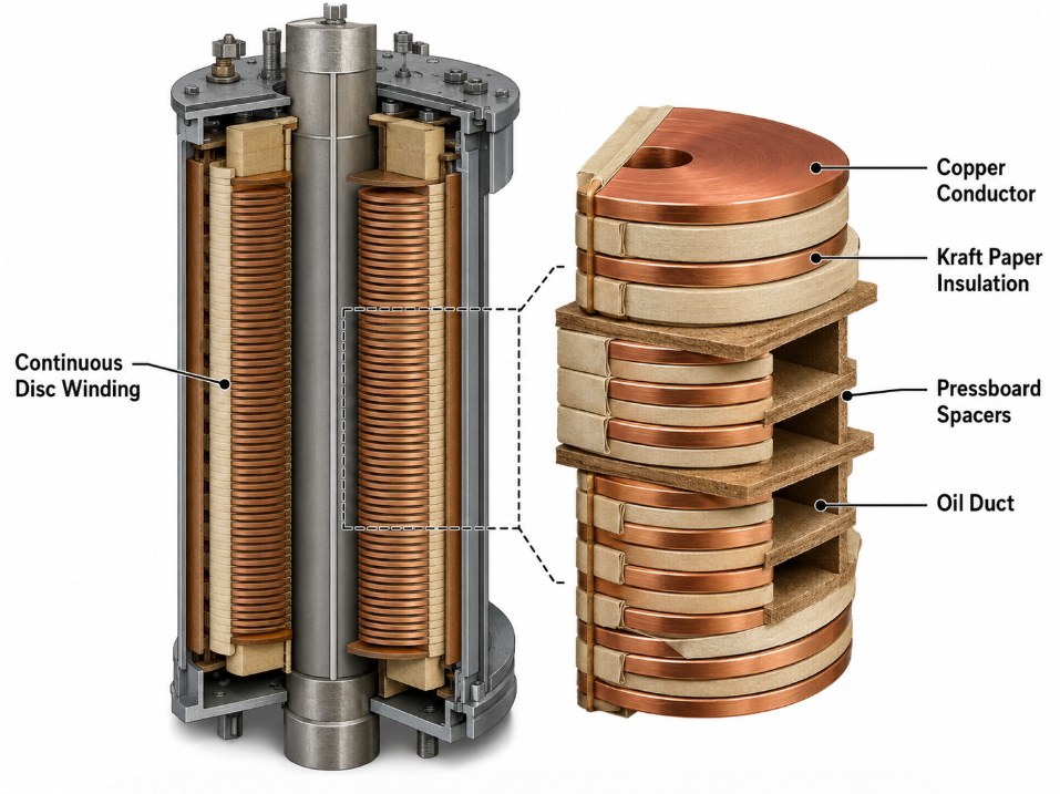
Power transformer winding configuration determines the unit’s voltage manipulation limits and its physical resistance to short-circuit deformation. Manufacturers wrap copper or aluminum conductors tightly in Kraft paper, organizing them into specific geometric patterns around the core legs.
Inspectors look directly at the winding geometry to assess build quality. Low-voltage windings typically use a helical configuration, placing them closest to the core to minimize insulation requirements. High-voltage windings sit on the outside, utilizing a continuous disc configuration. Spacers and pressboard blocks separate these discs, creating vertical and horizontal oil ducts. These precise physical gaps allow cooling fluids to penetrate the densest copper clusters.
A major diagnostic trap exists when testing these assemblies during a teardown. Repair engineers often encounter “The False-Megger Trap,” where surface moisture on the outer pressboard mimics a deep winding insulation failure. Dropping a megohmmeter reading from 500MΩ to 10MΩ often points to superficial humidity absorption rather than a permanent internal short. Baking the coil assembly in a vacuum oven at 85°C for 48 hours usually restores full dielectric strength, saving a $50,000 rewinding job.
The core dictates the efficiency of magnetic flux transfer and restricts eddy current losses. Builders construct this massive structure from thousands of ultra-thin, grain-oriented silicon steel sheets, each coated with a microscopic layer of carlite insulation.
Assembling these steel sheets requires exact physical overlapping known as step-lap joints. Technicians stack the sheets at the corners so the seams interlock like brickwork. This overlapping eliminates continuous air gaps in the magnetic circuit. QA inspectors zero in on the core clamping bolts and fiberglass banding during visual inspections. A loose core clamp generates severe mechanical vibration at 60Hz, eventually eroding the carlite coating and triggering localized overheating.
Power transformer bushings carry high-voltage current through the grounded steel tank without causing a flashover. These massive cylindrical structures act as isolated bridges, handling immense electrical stress gradients at the exact point where the internal wiring connects to the external grid.
By 2026, premium grid operators demand Smart Resin Impregnated Paper (RIP) bushings over legacy Oil Impregnated Paper (OIP) models. RIP bushings feature a solid epoxy-resin core embedded with ultra-high frequency (UHF) sensors. These sensors detect partial discharge spikes inside the bushing layers before the insulation catastrophically explodes. The solid-state nature of RIP totally eliminates the risk of oil leakage through degraded gaskets.
| Material | Leakage Risk | Sensor Integration | Maintenance Frequency |
|---|---|---|---|
| Smart RIP | Resin-impregnated paper, oil-free insulation system | Low; no internal oil reduces leakage and fire risk | High; supports embedded sensors for temperature, partial discharge, capacitance, and power factor monitoring |
| Legacy OIP | Oil-impregnated paper with insulating oil | Medium to high; aging seals and oil expansion can cause leaks | Limited; usually requires external monitoring devices or periodic offline testing |
Hardware tear-downs frequently reveal human error at the bushing flange. Installers routinely over-torque the base bolts during field assembly. Applying 80 Nm of torque instead of the specified 45 Nm fractures the lower porcelain weather shed or cracks the epoxy base. These micro-cracks remain invisible to the naked eye but allow moisture penetration, leading to internal tracking and eventual dielectric failure.
The power transformer cooling system extracts extreme heat from the core and windings, transferring it to the ambient air. Substation units rely on a combination of liquid immersion, pumps, and external finned radiators to prevent the internal temperature from exceeding 105°C.
Cooling configurations directly dictate the physical layout of the external hardware. ONAN (Oil Natural Air Natural) systems rely purely on convection; hot fluid rises to the top of the tank, flows into the radiators, cools, and sinks back to the bottom. ONAF (Oil Natural Air Forced) systems bolt massive industrial fans onto the radiator banks to aggressively pull air across the fins. Teardown crews inspect the mechanical impellers inside forced oil pumps for cavitation damage, which leaves distinct pitting marks on the brass blades.
The current shift toward biodegradable synthetic ester fluids alters hardware requirements. Esters possess a higher kinematic viscosity than traditional mineral oil. Engineers must install wider radiator ducts and uprate the pump motors to push this thicker fluid through the winding channels. Identifying the exact fluid type during a teardown dictates how inspectors handle the hazardous materials protocol.
The OLTC physically adjusts the transformer’s voltage output without interrupting the load current. It operates by mechanically switching the connection point across different turns of the regulating winding.
This component houses the highest number of moving parts inside the transformer. The diverter switch contacts take the brunt of the physical wear, enduring thousands of electrical arcs per year. Tungsten-copper alloy tips handle the arcing, but they vaporize slightly with each operation. Maintenance engineers extract the diverter switch assembly from its separate oil cylinder specifically to measure contact wear and filter out the carbonized oil sludge created by the arcs.
The conservator tank accommodates the physical expansion and contraction of the insulating fluid as load temperatures fluctuate. Mounted high above the main tank, this cylindrical drum ensures the core and windings remain permanently submerged.
A rubber air cell (bladder) sits inside the conservator to prevent atmospheric oxygen from mixing with the fluid. The breather pipe connects the inside of this bladder to the outside air, forcing incoming air through a silica gel canister. QA inspectors visually check the silica gel crystals. Blue or bright orange crystals indicate active moisture defense, while pale pink signals the gel is saturated and the fluid inside the tank is actively degrading.
The Buchholz relay functions as the primary mechanical fault detector, sitting in the pipe between the main tank and the conservator. It uses physical displacement to trigger alarms or trip the circuit breaker.
Minor internal faults, such as partial discharge, break down the insulating oil and generate hydrogen gas bubbles. These bubbles float up the pipe and accumulate inside the relay chamber, slowly dropping a mechanical float switch. Massive faults, like a short circuit, create a violent physical oil surge. The surge forcefully strikes a baffle plate inside the relay, instantly tripping the transformer offline. Post-mortem inspectors always extract gas from the top petcock of a triggered Buchholz relay; the chemical signature of that gas tells them exactly which internal component burned.
What is the difference between core type and shell type transformers?
Core type transformers wrap the windings around the outer legs of the steel core. Shell type transformers surround the windings with the steel core. Core types offer easier physical access for maintenance and winding inspection, making them the standard for high-voltage grid applications.
How do power transformer bushings fail?
Bushings fail physically through degraded sealing gaskets, allowing moisture ingress. Electrically, they fail due to partial discharge eating through the internal capacitive grading foils. External physical damage from wildlife or over-torqued mounting bolts also accounts for a massive percentage of field failures.
What causes power transformer winding configuration to deform?
Through-fault short circuits send massive current spikes through the coils, generating extreme electromagnetic forces. If the physical clamping structures (tie rods and blocks) lack proper tension, these forces physically warp and crush the copper coils, instantly destroying the internal paper insulation.
Why do modern power transformer cooling systems use ester fluids?
Synthetic ester fluids possess a flash point above 300°C, drastically reducing the risk of a substation fire compared to standard mineral oil (flash point 140°C). They are also fully biodegradable, eliminating the need for massive concrete environmental containment pits around the transformer base.
Can you visually inspect the inside of a power transformer without draining it?
You cannot fully inspect the winding configuration or the lower core joints without draining the fluid. Technicians can use boroscope cameras inserted through top inspection plates to check upper clearances and tap changer leads, but thorough structural validation requires a complete fluid drain and core extraction.
Discover The Function Of An Isolation Transformer Via 7 Core Examples. Block Ground Loops And Stop Electrical Noise.
View detailsHow To Test A Power Transformer And Tell If Yours Is Bad. Master Pro Multimeter Tests And Avoid Phantom Voltage.
View detailsMaster Power Substation And Power Grid Transformer Specifications To Prevent VFTO And Parallel Mismatch Failures.
View detailsMaster Power Transformer Basics And Definition. Discover Core Functions, The V-I-C Model, And Avoid Nameplate Traps.
View detailsPlease fill in the arithmetic result.
The calculation is incorrect, please fill it in again.