 BBELC
BBELC
Power Transformer Operation And Maintenance: Life Expectancy
6Optimize Power Transformer Operation And Maintenance To Extend Life Expectancy And Defer CAPEX Replacements.
View details
Search the whole station
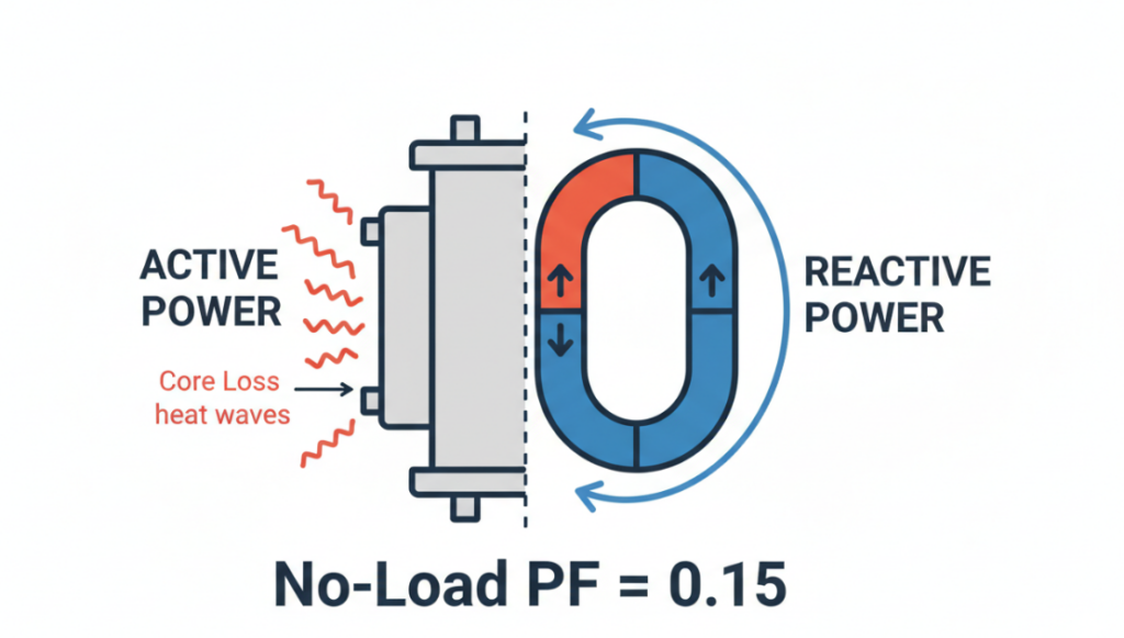
The transformer absolutely uses power without load, and its power factor at no load lags 0. 1 to 0. 2. When all plant machinery is shut down, the transformer still draws a continuous magnetizing current from the grid to maintain its magnetic core field. This creates a serious mismatch: a very small amount of active power (kW) is consumed as heat through the core lag, while a large amount of reactive power (kVAR) is pulled to maintain flux. In 2026, utilities are deploying high-frequency smart meters to penalize this off-peak reactive pumping. Every weekend your facility is vacant, you could be paying thousands of dollars in invisible utility fines. This is the exact blueprint my energy audit team uses to isolate, calculate and eliminate these hidden off-peak charges.
MAP Framework: Diagnostic Empty Facility Power Drain
Facility managers cannot address off-peak energy losses because they treat all electricity bills as a single monthly figure. My team uses MAP. (magnetized, active, penalized) framework to isolate the specific costs incurred when the building is vacant.
Step 1: Separate the excitation current (“M”)
In the case where the secondary side main breaker is completely opened, the current flowing into the primary side must be measured. People often ask: Does the transformer consume electricity when it is not loaded? The answer is yes, usually 1% of its full load rated current is 2%, just to keep the core magnetized. This current is almost entirely reactive. It has no useful work, no motor, and the lamp has no bulb, but it takes up the capacity of the utility line.
Step 2: Track the effective core loss (“A”)
The physical core of a transformer heats up even when it is idle. The alternating magnetic field creates friction (hysteresis) at the atomic level and induces tiny stray currents (eddy currents) within the metal. In this state, a standard 1500 kVA dry-type transformer consumes approximately 3 to 5 kW of continuous active power. If the power is kept 24/7 without load, this is equivalent to 43,800 kWh of pure heat waste per year.
Step 3: Calculate the reactivity penalty (“P”)
The power factor of the transformer at no load determines the economic loss you face. Since the active power (kW) is very small compared to the excitation reactive power (kVAR), the resulting power factor angle is very steep-usually hovering around 0.15. The utility meter immediately records this poor power factor. If your utility contract includes kVARh fines or kVA minimum requirements, your empty transformer will actively trigger these fines every night.
Real-world data: The $14,200 weekend leak
Our team recently audited a secondary automotive stamping plant in Ohio that was struggling with the new 2026 utility tariff structure. The facility conducts one shift Monday through Friday.
Plant managers think their energy costs are down to zero over the weekend. We installed sub-meters directly on its 2500 kVA cast resin transformer. The data proves otherwise. The transformer is completely unloaded for 114 hours per week. During this period, it consumed 7 kW of active power (core loss) and 45 kVAR of reactive power. Power factor locked at 0.15.
The utility charges a penalty of $1.20 per kVARh below the 0.90 total facility power factor threshold. The exposed transformer reduced the power factor to 0.15 over the weekend, as the plant’s main capacitor bank automatically shuts down.
We recorded a direct loss of annually 14,200-3,500 from wasted kW (heat) and a pure kVAR reactivity penalty of $10,700. We solved this problem by installing a small fixed 50 kVAR capacitor dedicated to the primary side of the transformer, which immediately offset the weekend penalty.
| State (Loaded vs. No-Load) | Active Power (kW) | Reactive Power (kVAR) | Power Factor | Monthly Utility Fine |
| Loaded | 1,840 | 784 | 0.92 | $0 |
| No-Load | 4 | 26 | 0.15 | $890 |
3 Expert Trap Energy Auditors Miss 2026
The energy audit needs to see the main electrical panel. Most standard energy software calculates transformer backup losses completely incorrectly. This is a trap you must avoid.
Pitfall #1: Relying on a Primary Auto-PFC Bank
The automatic power factor correction (PFC) group is designed to track the motor load. When your device shuts down, the PFC controller will see zero load and turn off all capacitor steps. This leaves your main step-down transformer with no compensation at all. You must install a small fixed “magnetized” capacitor that is permanently kept online to offset the reference kVAR of the transformer.
Trap 2: Ignore Primary Side Switch Solution
Engineers kept the main medium voltage switch off because they were worried about inrush current when restarting. Modern intelligent circuit breakers with point-on-wave switches eliminate this risk. If the secondary facility building is vacant for 3 months, the correct engineering choice is to disconnect the transformer from the primary side. Keeping it active just to power a few exit signs was a mathematical error; moving these emergency loads to a separate microcircuit.
Trap 3: Using Pre-2023 DOE Efficiency Criteria
Older transformers use silicon steel cores with substantial hysteresis losses. The 2026 standard for high efficiency facilities uses an amorphous metal core. These modern cores can reduce no-load active power loss by up to 70%%. If your facility runs intermittent loads (such as a stadium or seasonal cold storage), replacing old transformers with amorphous iron core units can achieve a return on investment in three years only through off-peak savings.
FAQ
What causes a low power factor without load transformer?
The low power factor is caused by the advantage of the magnetizing current. With no load drawing active power (kW) to balance the equations, the transformer draws only the reactive power (kVAR) needed to maintain its internal magnetic field, reducing the power factor to 0.1 or 0.2.
How to reduce the no-load loss of transformer?
You can reduce no-load losses by three main methods: installing fixed capacitors on the primary side to correct for non-peak power factor, upgrading to amorphous metal core transformers that inherently have lower hysteresis losses, or using smart primary switches to disconnect the transformer during long periods of vacancy.
Does closing the secondary circuit breaker stop the transformer supply?
Closing the secondary circuit breaker prevents load-related copper loss, but does not prevent the transformer from using the power supply. The primary winding remains energized, continuing to draw core loss real power and magnetized reactive power directly from the utility grid.
Is the no-load current active or reactive?
The no-load current is mainly reactive. Approximately 85% to 90% of this current is the magnetizing component (reactive) that generates magnetic flux, while only 10% to 15% is the core loss component (active) that overcomes friction in the core and generates heat.
Can a utility company detect a no-load transformer?
Yes. Modern high-frequency smart meters deployed by utility companies continuously record kvarh (reactive energy) and phase angle in real time. When your facility shuts down, they clearly see a sudden drop in power factor, which usually triggers an automatic off-peak penalty in your next billing cycle.
Optimize Power Transformer Operation And Maintenance To Extend Life Expectancy And Defer CAPEX Replacements.
View detailsMaster The 2026 Power Transformer Testing Procedure And Commissioning Tests Framework To Prevent Fatal Field Traps.
View detailsAdvanced Power Transformer Protection Schemes To Prevent Failure. Master 87T Relays And IEC 61850 Systems Today.
View detailsYou cannot use an autotransformer for electrical isolation. Autotransformers share a single, continuous winding for both the primary and secondary connections, meaning the input and output are electrically tied together. This direct pathway provi...
View detailsPlease fill in the arithmetic result.
The calculation is incorrect, please fill it in again.