 BBELC
BBELC
Substation Power Transformers: 7 Phase Shifting Flaws
34Comparing Stresses In Standard Power Transformers And Phase Shifting Transformers.
View details
Search the whole station
A standard power transformer testing procedure requires 18 specific electrical diagnostics sequenced strictly before, during, and after oil filling to validate insulation integrity, core health, and tap-changer functionality. Commissioning a unit in 2026 demands compliance with updated IEEE C57.152 and IEC 60076 guidelines, which mandate digital twin baseline synchronization alongside traditional Sweep Frequency Response Analysis (SFRA). Field contractors often fail Site Acceptance Tests (SAT) not due to faulty equipment, but because they execute diagnostic tests out of sequence. This guide strips away the academic theory and delivers the exact execution framework tier-one substation engineers use to validate high-voltage assets, preventing catastrophic energization failures and warranty disputes.
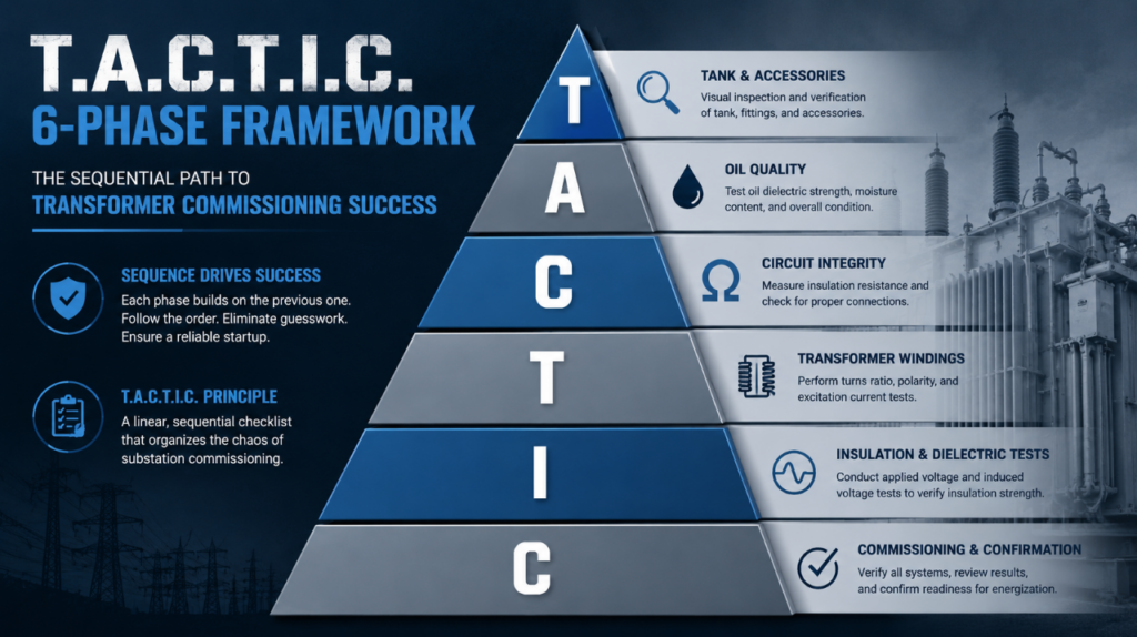
Sequence dictates success in power transformer commissioning tests. Testing insulation resistance before verifying oil dielectric strength yields useless data. The T.A.C.T.I.C. framework organizes the chaos of substation commissioning into a linear, sequential checklist.
Initial impact diagnostics determine if internal shifting occurred during transit. Substation crews must execute the Sweep Frequency Response Analysis (SFRA) before offloading the unit from the trailer. Comparing this site SFRA trace against the Factory Acceptance Test (FAT) baseline reveals microscopic core displacements or winding deformations. A deviation exceeding 1.5 dB in the mid-frequency range (20 kHz to 400 kHz) immediately triggers a manufacturer warranty hold.
Oil acts as both the coolant and the primary insulation medium. Crews execute vacuum cycles and oil filling procedures next. Technicians extract oil samples from the bottom valve to run Dissolved Gas Analysis (DGA) and dielectric breakdown tests. The 2026 standard strictly requires the dielectric breakdown voltage to exceed 60 kV for units rated above 230kV (per ASTM D1816 with a 1mm gap).
Transformer Turns Ratio (TTR) and winding resistance tests dictate the true condition of internal connections. Injecting a test voltage across the high-voltage terminals and measuring the low-voltage output confirms the phase relationship and vector group. The measured TTR value must stay within a strict 0.5% deviation from the nameplate rating. Simultaneous DC winding resistance checks identify loose bolted connections at the bushings.
On-Load Tap Changers (OLTC) cause over 40% of transformer mechanical failures. Static resistance testing is obsolete. Engineers now perform dynamic resistance measurements (DRM) to record the transition time and ripple current while the tap changer cycles through its positions. A transition time extending beyond 60 milliseconds indicates carbon buildup or worn diverter contacts requiring immediate mechanical adjustment.
Dielectric diagnostics quantify the degradation of paper insulation. The power factor (or Tan Delta) test applies 10kV AC to the windings to measure leakage current. A healthy new transformer registers a power factor below 0.5%. For deeper analysis, Dielectric Frequency Response (DFR) calculates the exact moisture content within the solid cellulose paper.
The final phase involves dry-running the mechanical protection systems. Contractors inject secondary current into the Buchholz relay, pressure relief devices, and winding temperature indicators to verify they trigger the breaker trip coils. Energizing a transformer without verifying these analog interlocks guarantees catastrophic destruction during an internal short circuit.
Understanding how to test a power transformer means knowing exactly how environmental variables manipulate test instruments. Field engineers routinely fall victim to three specific diagnostic traps.
Extremely low ambient temperatures skew dielectric frequency response algorithms. When technicians run DFR tests on a cold unit (below 5°C), the instruments often report a false moisture content exceeding 2.5%, simulating degraded insulation. The 2026 protocol requires engineers to apply a thermal correction factor utilizing the top-oil temperature curve, or temporarily heat the oil via a processing rig before finalizing the moisture assessment.
DC winding resistance tests leave the transformer core heavily magnetized. If a technician executes the single-phase excitation current test immediately after the DC resistance test, the residual magnetism causes massive current imbalances across the three phases. Crews must run a demagnetization cycle—applying a decreasing alternating DC voltage—prior to capturing excitation baselines.
Leaving internal Bushing Current Transformers (BCTs) open during high-voltage diagnostic testing generates lethal transient voltages. Test technicians assume factory workers shorted all unused BCT terminal blocks prior to shipping. Opening the control cabinet and physically verifying every single shorting link with a continuity tester prevents equipment destruction and fatal arc flashes.
Pass/fail criteria vary slightly based on geographical jurisdiction. The table below outlines the exact tolerance thresholds required for successful 2026 site commissioning.
| Test Type | 2026 IEEE Threshold | 2026 IEC Threshold | Critical Action |
|---|---|---|---|
| Transformer Turns Ratio (TTR) | ≤ 0.5% deviation | ≤ 0.5% deviation | Investigate tap changer settings and winding integrity if exceeded |
| Winding Resistance | Phase-to-phase deviation ≤ 2% | Deviation from factory baseline ≤ 2% | Verify connections and assess for loose joints or winding damage |
| Insulation Resistance (IR) | ≥ 1 GΩ (corrected to 20°C) | ≥ 1 GΩ (corrected to 20°C) | Dry-out or further dielectric testing required if below threshold |
| Power Factor / Dissipation Factor (Tan δ) | ≤ 0.5% | ≤ 0.5% | Inspect insulation system for contamination or moisture |
| Sweep Frequency Response Analysis (SFRA) | No significant deviation from baseline | No significant deviation from baseline | Mechanical inspection if signature changes are detected |
| Dissolved Gas Analysis (DGA) | Key gases within IEEE C57.104 limits | Gas concentration within IEC 60599 guidance | Investigate abnormal gas generation and determine fault type |
| Oil Dielectric Breakdown Voltage | ≥ 30 kV | ≥ 30 kV | Filter or replace oil if result is below minimum |
| Temperature Rise / Thermal Performance | Within nameplate rating | Within nameplate rating | Review loading and cooling system performance |
| Excitation Current | Deviation ≤ 10% between phases | Deviation ≤ 10% between phases | Check core grounding and winding condition |
| Grounding / Bonding Continuity | ≤ 1 Ω | ≤ 1 Ω | Repair or tighten grounding connections immediately |
What is the minimum acceptable insulation resistance for a power transformer?
The minimum acceptable value depends on the voltage class, but a general rule per IEEE standards dictates 1 Megohm per 1000 Volts of rating, plus 1 Megohm. A 138kV winding requires at least 139 Megohms. Industry best practice targets values exceeding 1000 Megohms for new installations.
Why do we perform Sweep Frequency Response Analysis (SFRA) before offloading?
SFRA acts as an internal acoustic and electrical fingerprint. Performing it before removing the transformer from the transport vehicle isolates transit-related damage. If the core shifted during transit, identifying it before lifting operations shifts liability back to the logistics provider rather than the installation contractor.
How long should a transformer sit after oil filling before testing?
A power transformer must sit for a minimum of 24 to 72 hours after final oil filling and vacuum cycles. This settlement period allows suspended gas bubbles—which severely compromise dielectric strength—to escape the liquid and migrate to the Buchholz relay or gas space.
Can you do Megger testing when a transformer is under vacuum?
No. Applying high voltage from a Megger (insulation resistance tester) while a transformer tank is under a deep vacuum causes immediate flashover and corona discharge. The lack of air or oil dramatically lowers the breakdown voltage, permanently destroying the paper insulation.
What is the difference between FAT and SAT in transformer testing?
Factory Acceptance Testing (FAT) occurs at the manufacturing facility under heavily controlled environmental conditions to prove design specifications. Site Acceptance Testing (SAT) takes place at the substation to verify the unit survived transport, assembly, and oil processing without degradation.
Why measure the polarization index (PI) on power transformers?
The polarization index measures the ratio of insulation resistance at 10 minutes to the resistance at 1 minute. A PI value below 1.2 indicates severe moisture ingress or conductive contamination in the windings. A healthy transformer typically yields a PI between 1.5 and 2.0.
Comparing Stresses In Standard Power Transformers And Phase Shifting Transformers.
View detailsAdvanced Power Transformer Protection Schemes To Prevent Failure. Master 87T Relays And IEC 61850 Systems Today.
View detailsDiscover The Function Of An Isolation Transformer Via 7 Core Examples. Block Ground Loops And Stop Electrical Noise.
View detailsLearn What Causes Power Loss In A Transformer. Explore Key Factors, Core Loss, And Expert Troubleshooting Skills.
View detailsPlease fill in the arithmetic result.
The calculation is incorrect, please fill it in again.