 BBELC
BBELC
Fuse Rating of Distribution Transformer & OLTC Setup: The Advanced Engineering Guide
17Master Fuse Rating Of Distribution Transformer & Oltc Distribution. Use Our 3-Node Sizing Guide To Stop Trips.
View details
Search the whole station
Ordinary power transformers in substations are used to honestly control the grid voltage level, but once power transmission is connected to a phase-shifting transformer (PST), the situation becomes extremely complicated and often introduces some serious electromechanical hazards that are difficult to detect. In a substation environment, the first priority of any power transformer is to achieve reliable energy routing. However, I have seen many on-site situations where when grid dispatch attempts to use phase-shifting configurations to force active power flows on parallel lines, it is actually triggering extremely complex magnetic flux and thermal stress ——extreme operating conditions that conventional transformers will never encounter in their lifetime. Ignoring these particular structural and operational defects, the results are often immediate: catastrophic insulation breakdowns, the destruction of equipment that can easily cost millions of dollars, and even widespread power outages on a regional basis.
Next, we will completely eliminate the most fatal electromechanical failures of high-voltage phase shifters and provide a practical engineering framework to completely solve these hidden dangers before the local power grid is paralyzed.
Every transformer in the substation infrastructure actually carries pressure to work within the strict thermal and magnetic field limits. The phase-shifting transformer used for power transmission deliberately manipulates the phase angle of the voltage to control the active power flow. This operation requires an extremely complex internal structure, usually with a series unit and excitation unit crammed into one or two fuel tanks. This “dual-core” design is equivalent to doubling the faulty node directly. I have found that many high voltage electrical contractors, who are usually accustomed to conventional equipment, often seriously underestimate how much dynamic stress the on-load tap changer (LTC) and those special winding configurations are subjected to during cross-phase regulation.
Standard Power Transformer vs. Phase Shifting Transformer Stresses
| Metric | Standard Transformer | Phase Shifting Transformer |
| Transient Overvoltage Vulnerability | Moderate: Standard insulation coordination is typically sufficient; surge propagation is relatively predictable. | High: Complex winding configurations and tap-changer leads increase vulnerability to switching and lightning surges, requiring specialized protection. |
| Winding Complexity | Low to Moderate: Typically consists of standard concentric primary, secondary, and sometimes tertiary windings. | Very High: Involves separate exciter and booster active parts, complex winding interconnections, and extensive internal cabling. |
| Core Saturation Risk | Low: Operates under stable, predictable voltage and frequency conditions with standard design margins. | Moderate to High: Increased risk due to phase angle variations, transient voltage imbalances, and potential susceptibility to geomagnetically induced currents (GICs). |
| Maintenance Frequency | Low to Moderate: Requires routine oil analysis and standard maintenance intervals, as tap changers (if present) operate less frequently. | High: Requires frequent inspection and maintenance, largely driven by the high duty cycle of the On-Load Tap Changers (OLTC) and the complexity of the auxiliary systems. |
Blind voltage regulation across extreme phase angles will instantly generate a huge circulation and directly burn the excitation unit. This is actually a common management loophole. Many substation electrical engineers cut and tap the joints just by staring at the trend request on the SCADA screen, without verifying the transient magnetization state of the iron core at that time. When the tap changer is operated under high load, the phase difference forces a huge circulation that is stuck between the series winding and the excitation winding. This current not only bypasses conventional differential relays, but often fuses the internal oil passage before the external alarm even reacts.
The asymmetric short-circuit force caused by external power grid failure can physically crush the complex voltage regulating winding of the phase shifter. In substation layouts, the winding geometry of standard transformers is relatively regular. But phase shifters rely entirely on extremely complex zigzag or interconnected winding traces in order to transform the phase. In the event of a short circuit with a large current, the electromagnetic force is completely uneven in squeezing these complex structures radially and axially. As soon as the winding twists and deforms, the outer insulation paper is completely destroyed, and the inevitable dead short circuit between turns follows.
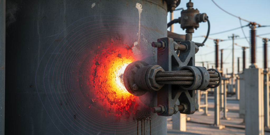
The leakage flux running out from the complex phase-shifting magnetic flux can induce severe local eddy currents on the tank wall and structural clamps. Adjusting the phase angle would have broken the magnetic field balance, preventing the main core from fully holding the magnetic field. These leakage flux are directly applied to the mild steel of the transformer tank. To be honest, without the precise installation of customized aluminum or copper magnetic shunt shielding layers at the leakage point, the temperature of the fuel tank steel plate can easily exceed 150°C. This will not only cause the surrounding insulating oil to age quickly, but also produce combustible dissolved gases that reach dangerous concentrations.
When making large phase angle adjustments, the excitation unit bears a disproportionate amount of thermal stress because it has to continuously absorb reactive power. I have come into contact with many power grid infrastructure plans, and they usually only look at the maximum active power throughput to choose the model, which is a pitfall. They usually ignore the massive reactive power of the internal circulation. The excitation core is almost magnetically saturated when the device is operating close to the maximum lead or lag angle. The huge amount of heat generated by this saturation cannot be discharged at all by ordinary ONAN (oil-immersed self-cooling) or ONAF (oil-immersed air cooling) cooling circuits.
If a phase-shifting transformer is installed near a series compensation transmission line or wind farm, it is very likely to inadvertently amplify the subsynchronous resonance. The series inductor and the capacitor of the long-distance transmission line built into the phase shifter touch each other, and at certain specific sub-synchronous frequencies, this LC circuit resonates. The resulting torsional oscillations are transmitted back and forth along the power grid, which can forcibly break the turbine shaft of the nearby generator. It is absolutely necessary for substation engineers to run a deep transient network analyzer (TNA) test before sending power.
The high electric field stress at the junction of the series unit and the excitation unit is rapidly accelerating the insulation breakdown of the oil channel. The electrical connection between these two independent cores is made by interconnected leads in extreme voltage gradients and covered with a thick insulating layer. Moisture and tiny cellulose particles naturally like to run towards these high-stress areas. Over time, these impurities build a conductive “bridge” between the oil gaps, triggering partial discharge. This thing nibbles silently at solid insulation until one day there’s a sudden catastrophic interphase flashover.
If the standard deviation dynamic protection scheme is applied to the complex winding topology of the phase shifter, it will be a huge protection blind spot. Because the phase angle is dynamically changing during operation, the ratio of primary to secondary current is completely nonlinear. Old electromechanical protection devices or basic digital relays cannot turn around at all, and the trip curve cannot be dynamically adjusted according to the real-time tap position. The result is that a minor fault like a short circuit in a single turn of the voltage regulating winding will not cause any response at all in the system until it deteriorates into a fire in the entire machine core.
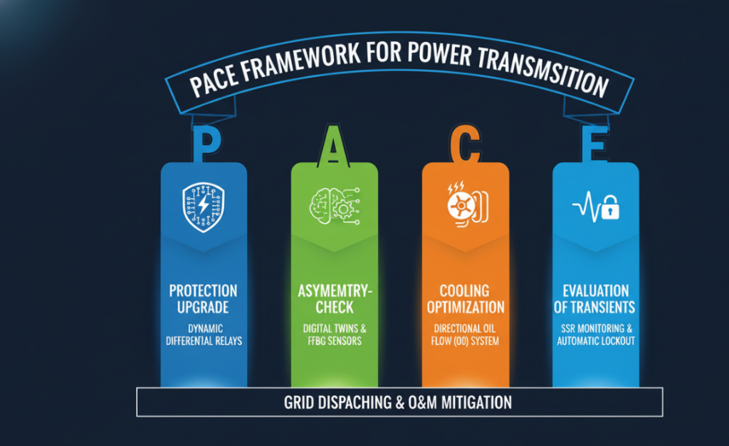
Using the usual maintenance logic to manage phase shifters, it’s only a matter of time before something happens. To preserve these core assets, I strongly recommend that power transmission practitioners directly apply this set of PACE Framework:
A while ago we came across a real example at a 400kV interconnected substation in West Texas, which completely confirmed why advanced monitoring of phase shifters in power transmission systems is necessary. The station has a 600 MVA dual-core phase shifter, and dissolved gas (ethylene and methane) indicators soar wildly whenever the tap changer exceeds a +10 degree lag position.
At the beginning the reports given by the contractors also wanted to attribute the cause to the ageing of ordinary insulating oil. Later, we retrieved the internal FBG sensor data for an in-depth investigation, and the truth came out: during the high-intensity cross-phase adjustment, the stray leakage flux had seriously saturated the clamping structure of the excitation core. Later, the engineering team installed a custom magnetic shunt on the fuel tank and cut it to PACE Cooling protocol (ODAF cooling instead), under this action, the hot spot temperature of the tank wall drops directly by 64°C, and the abnormal combustible gas also disappears completely. This intervention literally pulled a $5 million asset back from the brink of obsolescence.
The standard power transformers in substations are mainly designed to effectively increase voltage to meet long-distance transmission, or to reduce voltage for safe distribution to industrial and residential users. The core is to use the lowest line loss to achieve efficient power routing.
Because the phase-shifting transformer can force the active power flow “press” to a specific transmission line by changing the phase angle of the voltage. This move can directly avoid line overload and squeeze out the maximum capacity of the power grid, and solve the transmission bottleneck problem where standard voltage regulating transformers are completely helpless.
Most of them are because the complex internal winding cannot withstand the mechanical stress and is hard torn during a short circuit; or the circulation overheats during blind voltage regulation; or the unprotected magnetic leakage directly burns the tank wall.
Absolutely not. As the phase angle changes, the current and voltage ratio fluctuates all the time, and the standard deviation moving relay either alarms randomly or plays blind. Phase shifters need to be equipped with advanced differential relays that can focus on the tap position in real time and perform crazy internal recalculation compensation.
Just raise it like an ordinary up/down transformer. Many people simply do not do special condition monitoring of the interconnected leads between the series unit and the excitation unit. The final result is often sudden insulation breakdown, followed by a fire.
Master Fuse Rating Of Distribution Transformer & Oltc Distribution. Use Our 3-Node Sizing Guide To Stop Trips.
View detailsLearn What Causes Power Loss In A Transformer. Explore Key Factors, Core Loss, And Expert Troubleshooting Skills.
View detailsFind A Pad-Mounted Distribution Transformers Factory. Secure DOE 2016 And IEEE Units In 20 Weeks. Bypass Fake OEMs.
View detailsInside A Power Transformer: Teardown Of Seven Core Parts, Bushings, Cooling Systems And Winding Configurations.
View detailsPlease fill in the arithmetic result.
The calculation is incorrect, please fill it in again.