
 BBELC

Step Up Transformer: How To Verify It Is Compatible With Your System
The 1 equipment list reads “step-up transformer”, but does not indicate the access voltage, target bus voltage and load conditions. At this time, only by name selection, it is easy to mistake the change ratio for the whole equipment. First, draw the power supply, output terminal and operation mode on the same single-line diagram to determine which section of voltage conversion it bears.
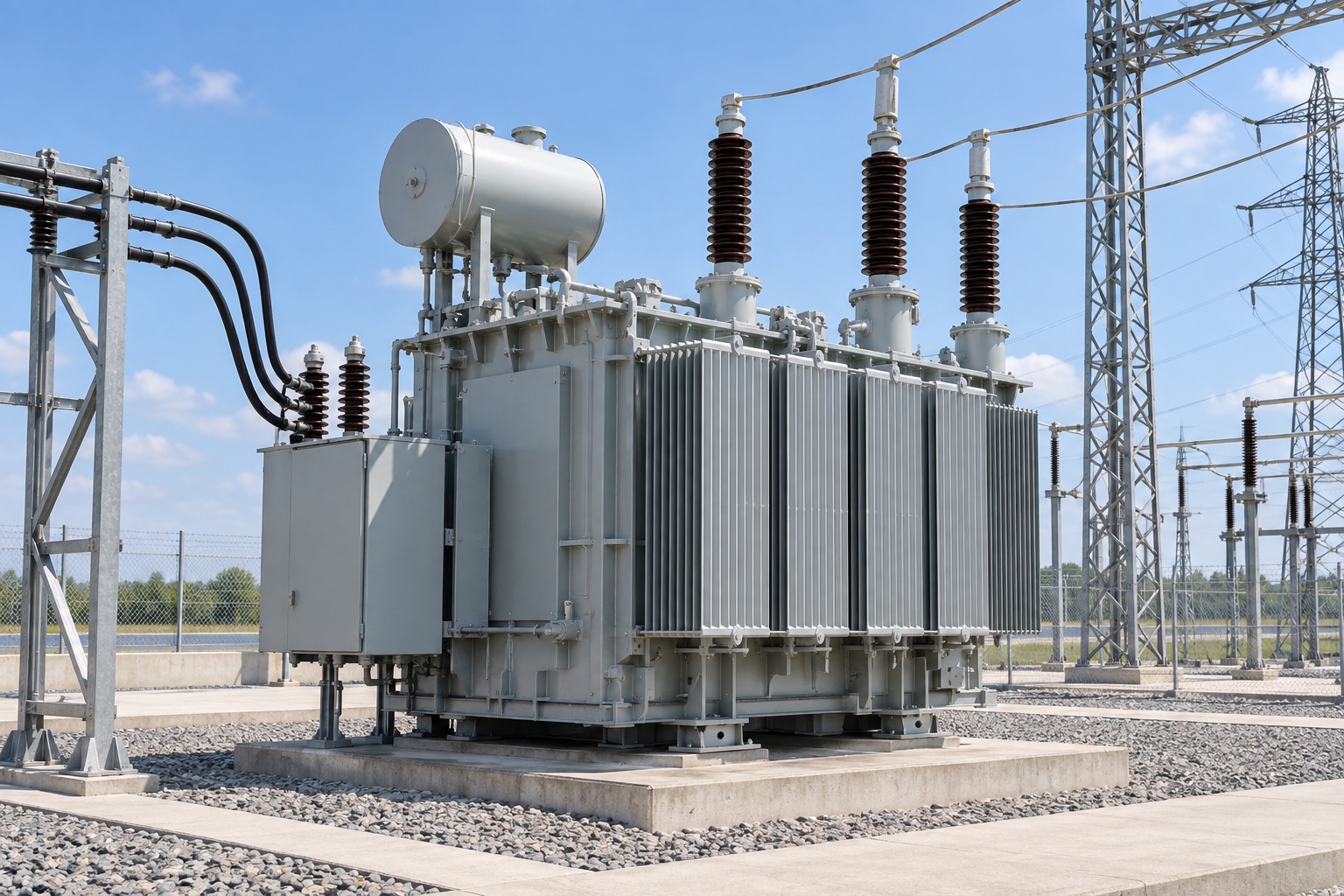
First, Return the Input and Output to the Actual System
Boost means that the output voltage is higher than the input voltage in the same direction of operation. The primary winding is connected to the power supply, and the secondary winding transmits power downstream; the primary and secondary windings are not fixed equal to the high voltage side and the low voltage side. Ideally, the ratio of the secondary voltage to the primary voltage is equal to the corresponding turns ratio. The high-voltage side usually has more turns and a smaller rated current, but this is only the starting point for explaining the voltage transition.
For example, if the design condition is to increase 400 V to 10 kV, the ideal voltage ratio is 25, and the output current is about 1/25 of the input current, ignoring losses. The voltage increase did not result in a 25-fold increase in power. The equipment is still subject to the rated capacity, rated current on both sides, temperature rise and insulation level, and the actual output active power will be deducted from the core and winding losses.
The step-up transformer in the list also indicates only one direction. Ask for the rated voltage, rated capacity, frequency, number of phases and tap position of each winding, and then check the actual voltage on the power supply side against the target output voltage. The no-load voltage calculated by the turns ratio is directly regarded as the on-load terminal voltage, which will leak the changes caused by winding resistance, leakage reactance, load current and power factor.
See Which Node It Will Connect To
When the generator set is boosted, the terminal voltage and the grid-connected voltage are two boundaries that must be clearly defined, and the maximum continuous capacity, short-circuit conditions and start-stop methods must be given. The wind farm may first rise to the medium voltage collection level near the unit, and then the main transformer of the booster station will receive the sending voltage. These two sections cannot be combined into the same equipment requirement because they are both called boosting.
PV and energy storage projects should also describe the inverter or converter interface, day cycle load, harmonics, reactive operation and reverse power conditions. In the industrial field, it is confirmed that the equipment or superior bus really requires higher voltage, and the system short-circuit capacity and grounding mode are checked. If these inputs have not been determined, a target voltage number is not sufficient to complete the selection.
Besides the Turns Ratio, What Else Needs to Be Verified?
The manufacturer is requested to submit the rated capacity, voltage and current on both sides, impedance, coupling group, tapping range, insulation level, cooling method and environmental conditions under the same working conditions. Impedance affects fault current and on-load voltage drop. The connection group involves phase relationship and system access. The insulation requirements of high-voltage windings also correspond to the maximum voltage and overvoltage conditions of the system. The “Boost” designation on the nameplate cannot replace these items.
If the program intends to reverse the existing step-down equipment, stop and check the nameplate wiring list and manufacturer’s instructions. Reverse wiring is not arbitrarily reversible: tap design, voltage regulation logic, protection direction, grounding, metering and winding thermal load may need to be re-checked. The number of turns originally arranged for the voltage drop on the buck side may also cause the high voltage output after reverse boost to be lower than the target value.
During acceptance, align the design voltage ratio, specified tap position and measured no-load ratio one by one, and check the voltage ratio, polarity, phase displacement and test records of the coupling group. What really determines whether this equipment is applicable is its output, tolerance and protection coordination under the specified load and system conditions of the project, not whether there is “boost” in the name “.