
 BBELC

Power transformer winding connection method: star and triangle
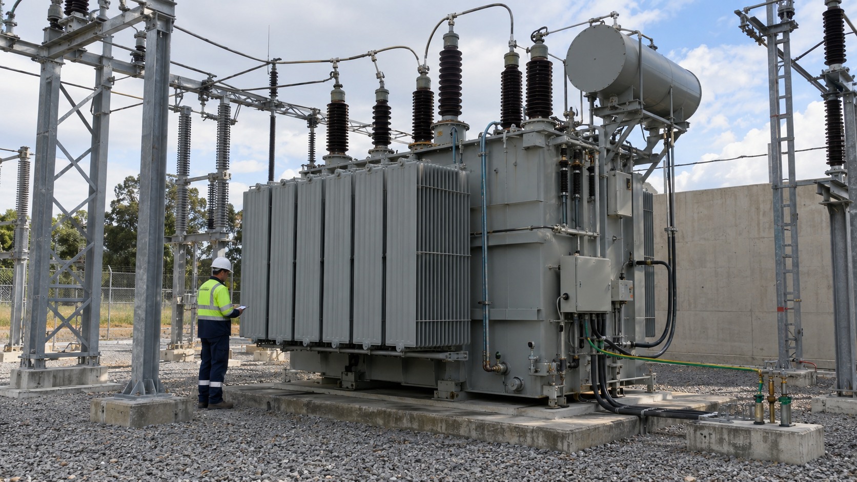
The winding connection method determines whether this transformer can be used correctly
When it comes to whether a three-phase transformer can be used, many people habitually glance at the capacity and voltage first, but often miss another crucial information on the nameplate ——winding connection group (that is, connection method). Also a three-phase transformer, the windings can be connected in star or triangle. These two connection methods directly determine the relationship between line voltage and phase voltage, which will then affect how the neutral point is drawn out, where the zero-sequence current goes, and how relay protection is coordinated. Therefore, if you want to determine whether a transformer is suitable for your current system, the capacity and voltage alone are definitely not enough. How the windings are connected must be calculated together.
The difference between a star and a triangle is a square root three
The most common connection methods for three-phase windings are star and triangle. The most intuitive difference between the two lies in the relationship between voltage and current: when connected in a star shape, the line voltage is 3 times the square root of the phase voltage, and the line current is equal to the phase current; if connected in a triangle shape, the situation is exactly the opposite, the line voltage is equal to the phase voltage, and the line current is 3 times the square root of the phase current. This relationship “root number 3” directly determines how much actual phase voltage and rated current the winding coil must carry. When calculating three-phase voltage and current, you should never just use a line voltage to make a blind comparison.
The connection group tightly binds the connection method and phase together
Just talking about a star or triangle is not enough, because how to connect the high and low pressure sides and how much phase difference there is between the two sides must be tied together. The “connection group number” on the nameplate does this job. It not only explains the connection method of the high and low voltage windings clearly, but also clearly marks the phase angle difference (phase shift) between the two sides. This thing is a core data for transformer parallel operation, system grounding, relay protection and harmonic calculation. For example, the most common “corner-star” connection method in power distribution is naturally accompanied by a fixed phase difference, which is an inherent property of the connection group itself. If two transformers, even if their rated voltage and capacity are exactly the same, cannot be directly connected in parallel, or even connected to an existing system, as long as the connection groups do not match or the phase difference is incorrect.
The winding connection method is stuck to the neutral point and zero sequence channel
How the winding is connected also directly determines the way out of the neutral point and the channel of the zero-sequence current. The star connection method can easily lead out a neutral point, which is why the distribution network is full of people using the “corner-star” connection method—— diagram, which means that there can be a ready-made neutral point on the low-voltage side. To figure out whether a new neutral point is needed or what to choose for the secondary side grounding system, the first step is to finalize the winding connection method. Conversely, if you absolutely must reverse the power supply of a “corner-star” transformer (low voltage in and high voltage out), then the system engineer will have to overturn and recalculate its neutral grounding method, zero-sequence channel, phase difference, and protection polarity. Don’t make up the original plan.
Phase-shifted rectifier transformer: relies on multiple winding groups “harmonic cancellation”
When facing rectified loads, the winding connection method also has a special “unique” skill. Take the phase-shifted rectifier transformer used for frequency conversion and speed regulation as an example. The high-voltage side winding can be connected in a triangle or star shape according to the system requirements, while the low-voltage side will create several independent three-phase windings to forcibly create the required phase shift angle. When these secondary windings with different phases work in conjunction with the rectifier bridge, they can cleverly cancel out some low-order characteristic harmonics on the common AC side, thereby improving the power factor and power quality on the input side. To put it bluntly, the transformer winding configuration of this type of equipment has long been used not only for voltage transformation, but also to provide precise phase relationships for a bunch of rectifier units.
Parallel connection and selection, winding connection method must be strictly seamless
When it comes time to connect to the grid or run multiple units in parallel, the winding connection method must be consistent, which becomes insurmountable “red line”. When transformers are connected in parallel, you need to thoroughly check the voltage ratio, polarity or phase sequence, connection group and phase difference, frequency, impedance voltage (percentage impedance), and capacity difference. If any one of these indicators is not correct, the load distribution will be uneven at best, and the circulation combustion equipment will be directly produced at worst. The same principle applies when selecting a type. The connection group must be strictly aligned with the system’s neutral point, grounding method, relay protection, phase, and parallel connection requirements. It is by no means just a random unit if the capacity is sufficient.
To summarize a sentence
So, the winding connection method looks like a few inconspicuous letters on a nameplate, but in fact it is like a root wire, stringing together the voltage relationship, phase, ground, harmonics and protection. Whether you are building a new project or replacing an old transformer, running in parallel or with a rectified load, first understand the winding connection method and configuration of the power transformer. Only when the bottom line is clearly laid out can the subsequent selection and operation not be overturned in details.