
 BBELC

Regulating Transformer in Power System: Tap Selection
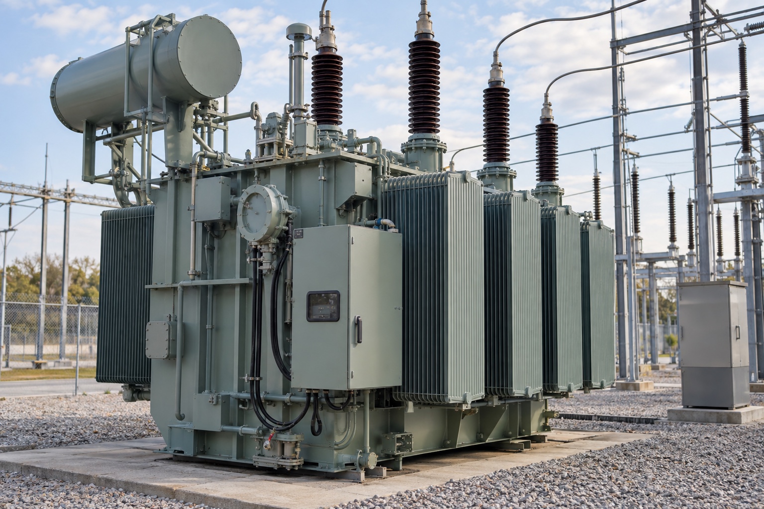
When the bus voltage looks high or low, it is easy to see the problem simply by directly requiring the transformer to “adjust the 1 gear. Supply side deviation, load variation, line voltage drop and load power factor all affect the receiving terminal voltage. The tap position can alter the turns ratio, but it cannot replace a comprehensive assessment of the entire power supply circuit.
When you see regulating transformer in power system in the project file, what you really need to confirm is not whether the name sounds like it has voltage stabilization capability, but how the equipment is regulated, what state it is allowed to operate in, and how much voltage change it faces.
The Tap Changer Alters the Effective Number of Turns.
A voltage-regulating transformer or a transformer with tap changers adjusts the output voltage by changing the effective number of turns. This operation addresses the voltage magnitude matching issue. It does not automatically provide outage life, nor is it equivalent to handling sags, surges, harmonics, or all power quality issues.
The no-load voltage ratio can help check the number of winding turns and tap position, but the on-load terminal voltage is also affected by short-circuit impedance, load current and power factor. When the inductive load increases, the secondary terminal voltage usually drops; under some capacitive conditions, the drop may be reduced, or even the voltage rises. Therefore, the nominal input voltage can not only be multiplied by the nominal ratio, as the actual output of all operating points.
First, Determine Whether Load Switching Is Required.
The demarcation between non-excitation tap and on-load tap is clear: the non-excitation tap can only be operated after the transformer is completely isolated from the system power supply; the on-load tap changer can change the effective number of turns without interrupting the load current.
If the tap is mainly used for installation and commissioning, seasonal adjustment or long-term voltage matching, and there is a power outage window on site, no excitation scheme may be sufficient. Only when the grid voltage or load changes continuously during operation and the downstream cannot accept power outage switching, it is reasonable to take on-load voltage regulation as the key scheme. Here, we should not only look at the word “adjustable”, but also include the operating frequency, control logic, protection interface and maintenance conditions.
On-load switching does not mean that the equipment can operate outside its specified limits and switch frequently. The contact wear, poor contact, transmission failure or wrong position of the tap changer may cause overheating, arc, abnormal voltage and even shutdown. When selecting the type, it is necessary to ask about the switch form, allowable operating conditions, position feedback, alarm and maintenance responsibility, instead of waiting for the operation to supplement the control strategy.
Specify the Voltage Regulation Range as a Verifiable Parameter
In the 1 executable technical conditions, the positive and negative adjustment range, number of stages, percentage of each stage, and whether to use non-excitation or on-load tap shall be stated at the same time. The range and step size should be determined jointly by the grid voltage variations, load voltage drops, and the allowable voltage range of downstream equipment.
Also, pay attention to the gear position. The tap position changes the effective number of turns and the voltage per turn, but whether the “upshift” or “downshift” will increase or decrease the output must be based on the nameplate wiring chart and manufacturer’s instructions. It is easy to continue to adjust in the wrong direction when the voltage has deviated by the judgment of the on-site personnel by habit.
When verifying the voltage regulation, be sure to specify all the conditions. The load current, power factor, temperature and tap position are different, and the results cannot be directly compared together. Only two nominal voltages are provided in the inquiry phase, and the manufacturer cannot confirm the loaded output under actual power fluctuation, let alone judge whether the voltage regulation range is sufficient.
System Conditions Determine the Voltage Regulation Logic
The voltage regulation device is not an independently operating voltage knob. Before parallel operation, it is necessary to confirm that the transformation ratio and tap position, phase sequence and polarity, phase displacement of the coupling group, frequency and percent impedance are compatible with each other, otherwise circulation or uneven load distribution may occur.
When there are distributed photovoltaic, energy storage or regenerative loads, check the direction of bidirectional power flow, low load high voltage, voltage regulation logic, reverse protection and metering. At this point, the shift-point determination method previously based solely on unidirectional power delivery may no longer be applicable. The control scheme should be based on the actual power flow state to determine the action, rather than just staring at a bus voltage value.
Even After Commissioning, the Position and Status Still Need to Be Monitored.
Before putting into operation, it shall be confirmed that the installation, tap position, phase sequence, coupling group, protection setting value, cooling, temperature control and grounding of accessories are correct. During operation, voltage, current, temperature, cooling status, and tap position should be recorded and monitored together. Only record the output voltage, but do not know the load and gear at that time, it is difficult to judge whether the change comes from the system or the equipment.
The power-off, isolation and power test procedures must be performed for non-excitation tap-changer operation; the on-load tap-changer shall be managed according to its independent operation and maintenance requirements. The re-shipment after maintenance is also to reconfirm that the wiring and tap are in the correct position, protection and cooling have been restored.
The final choice can fall into a direct question: whether the system must continuously correct the voltage during normal operation? If not, give priority to writing out the power failure operation boundary and the correct gear; if necessary, write out the scope, step difference, control, protection and maintenance conditions of on-load tap into the technical specification completely, and then talk about the equipment model.