
 BBELC
BBELC
medium voltage dry type transformers
cnbbelc designs and manufactures medium voltage dry type transformers for power distribution, electrical isolation, medium voltage drives, multi-pulse rectifier systems, heavy-duty EV charging, shore power, and other engineered power-conversion applications.
Choose cast-resin or non-encapsulated insulation, natural-air, forced-air, or air-forced/water-forced cooling, and the winding arrangement required by your single-line diagram. Voltage, capacity, impedance, vector group, phase displacement, enclosure, terminals, and site conditions are coordinated as one transformer design.
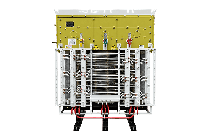
Phase-Shifting Rectifier Transformer for Medium Voltage Drive Systems
What Medium Voltage Dry Type Transformers Do
A medium voltage dry type transformer transfers AC power through a laminated magnetic core and insulated windings while keeping the active part free of insulating liquid. Solid insulation and air, or a defined gas path, provide the principal insulation and cooling functions. This construction removes the insulating-liquid containment system and supports installations where fire strategy, leak prevention, indoor placement, or maintenance access shapes the equipment choice.
The transformer can step voltage up or down without changing frequency. Separate primary and secondary windings can also provide galvanic isolation. A multi-winding phase-shifting design adds controlled phase relationships for multi-pulse rectifier bridges. The downstream rectifier produces DC power; the transformer supplies the required voltage, isolation, impedance, and phase configuration.
Dry type describes the insulation and cooling medium, not one universal winding construction. Cast-resin coils, vacuum-pressure-impregnated windings, open ventilated designs, non-ventilated enclosures, and closed-loop air-to-water systems behave differently in moisture, dust, heat, and restricted spaces. The selected construction must match the electrical duty and the installation environment.
Functions Available in One Engineered Design
- System impedance: Coordinate fault current, voltage drop, rectifier commutation, and parallel operation with the rest of the power system.
- Thermal management: Select natural air, forced air, or a closed air-to-water cooling loop for the specified losses and site conditions.
Choose the Design by Electrical Duty
The correct transformer type follows the job shown on the single-line diagram. Capacity and primary voltage narrow the field, while the load waveform, isolation requirement, grounding method, installation environment, and available cooling determine the workable construction.
| Design | Primary duty | What changes in the design | Typical project fit |
|---|---|---|---|
| Cast-resin distribution transformer | Step medium voltage down for facility distribution | Resin-cast winding insulation, vector group, taps, impedance, enclosure, losses, and terminal arrangement | Commercial and industrial indoor distribution |
| Dry-type isolation transformer | Separate source and load circuits while converting or maintaining voltage | Independent windings, insulation level, grounding arrangement, optional electrostatic shield, and output voltage regulation | Industrial controls, sensitive loads, commercial systems, and specialized power supplies |
| Phase-shifting rectifier transformer | Feed multi-pulse rectifier bridges | Multiple secondary windings, phase angles, bridge loading, winding-current balance, non-sinusoidal loss allowance, and system impedance | Medium voltage drives, rectifier systems, charging infrastructure, and test power systems |
| Four-quadrant phase-shifting transformer | Support a drive with motoring and regenerative power flow | Bidirectional duty, split winding arrangement, impedance balance, protection, and converter coordination | Mine hoists, cranes, propulsion, dynamometers, and regenerative drives |
| Delta-core phase-shifting transformer | Fit phase-shifting duty into a restricted width | Open delta-stacked core, winding geometry, ventilation path, and mechanical dimensions | Skids, containers, equipment rooms, and other width-constrained installations |
| AFWF dry-type rectifier transformer | Carry high rectifier power in a protected closed cooling circuit | IP54 enclosure, internal forced-air path, air-to-water heat exchanger, water conditions, alarms, and interlocks | Dusty, corrosive, or thermally constrained industrial sites |
Medium Voltage Dry Type Transformer Products
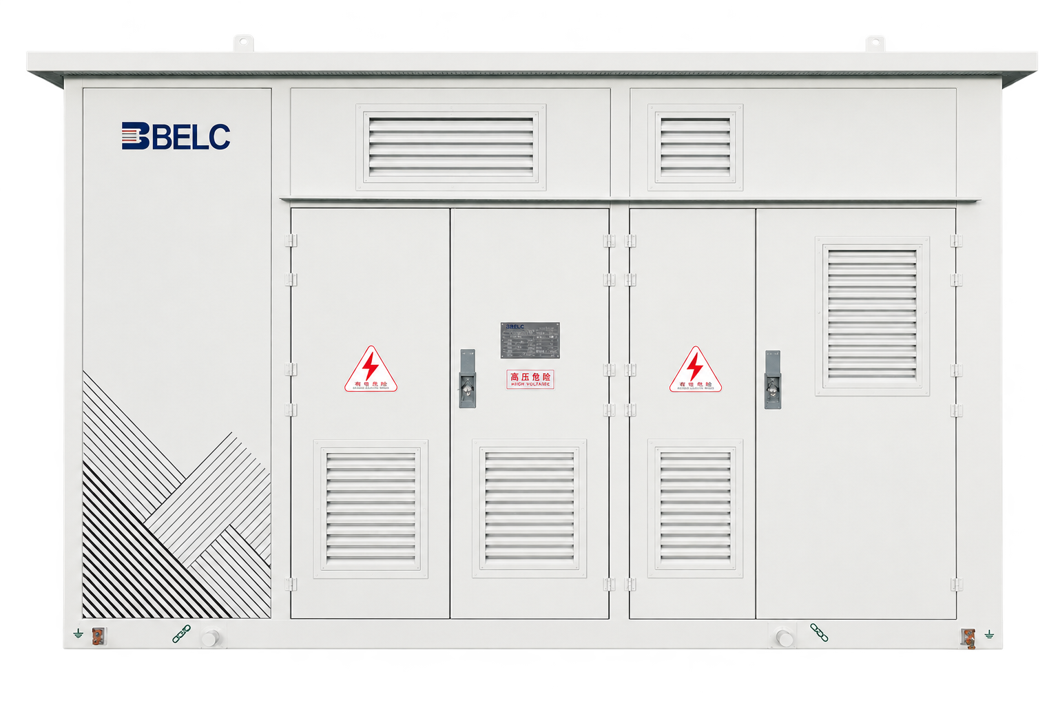
PHASE-SHIFTING RECTIFIER TRANSFORMER FOR HEAVY-DUTY EV CHARGING
This dry-type phase-shifting transformer supplies multiple rectifier inputs in high-power charging and battery-swap systems. The winding arrangement combines medium-voltage conversion, galvanic isolation, and the phase relationships required by 12-pulse or 24-pulse charging architectures.
- Rated voltageUp to 10 kV
- Rated capacityUp to 2,500 kVA
- InsulationClass F or H

Three-Phase Cast Resin Dry-Type Distribution Transformer
This three-phase distribution transformer uses cast-resin winding insulation for indoor medium-voltage power distribution. The design can be coordinated with the required primary and secondary voltages, vector group, taps, impedance, enclosure, losses, dimensions, and terminal interface.
- Rated voltageUp to 35 kV
- Listed capacity100 kVA to 20 MVA
- ConstructionCast-resin, Class F or H

Dry-type Isolation Transformer
Independent primary and secondary windings provide galvanic isolation while the transformer maintains or changes voltage. The design can include a project-defined vector group, impedance, enclosure, grounding arrangement, and electrostatic shielding when the specified common-mode performance requires it.
- Rated voltageUp to 35 kV
- Listed capacity100 kVA to 12 MVA
- ConstructionThree-phase cast-resin, Class F or H
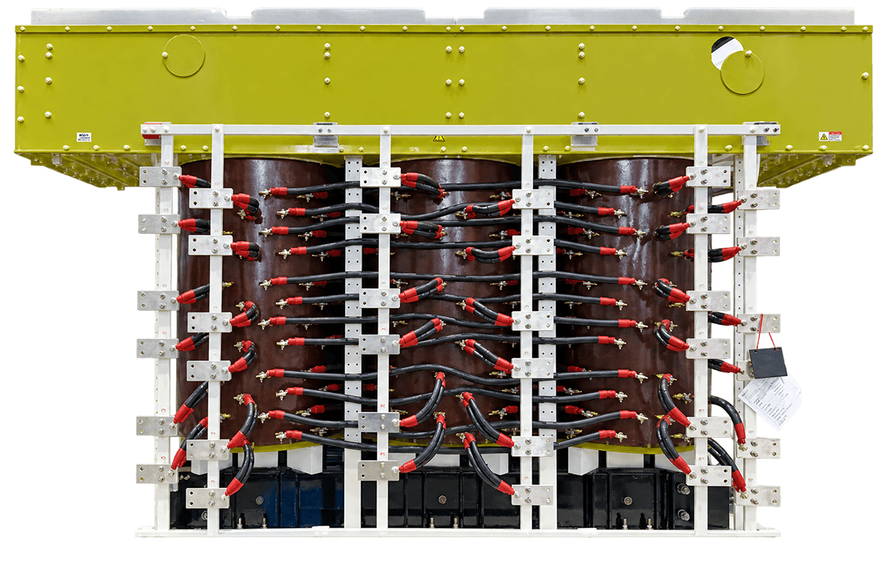
11000kVA × 4 Dry-Type Rectifier Transformer for medium voltage drives
Four 11,000 kVA dry-type rectifier transformer units can be arranged as a 44,000 kVA power-conversion system for a large medium voltage drive. Each unit divides the low-voltage side into three main groups, with four subgroups and one additional subgroup in each main group, so the transformer arrangement can be coordinated with the converter topology.
- System arrangementFour 11 MVA units
- Combined capacity44 MVA
- Rated voltageUp to 10 kV
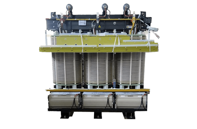
Dry-Type Isolation Transformer for Shore Power
This isolation transformer interfaces shore-side conversion equipment with a vessel power system. The design supports 50 Hz and 60 Hz operation and can use a 6 kV or 6.6 kV primary arrangement, while corrosion-resistant hardware, treated coils, coated core surfaces, plated busbars, and protected insulation edges address the defined marine environment.
- Rated voltageUp to 35 kV
- Rated capacityUp to 12 MVA
- Frequency50/60 Hz design
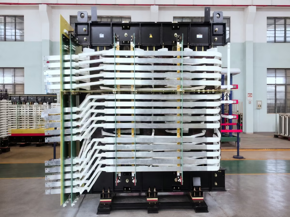
AFWF dry-type rectifier transformer for medium-voltage drives
The transformer operates inside an IP54 enclosure with a closed internal air circuit and an air-to-water heat exchanger. Forced air removes heat from the windings and core, while the water circuit transfers that heat out of the enclosure without continuous exchange between the internal cooling air and the surrounding atmosphere.
- Rated voltageUp to 35 kV
- Rated capacityUp to 20 MVA
- Cooling and enclosureAFWF, IP54
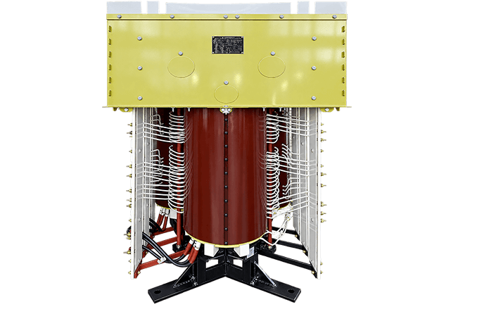
Delta-Core Phase-Shifting Rectifier Transformer
An open delta-stacked core and phase-shifting windings reduce transformer width for installations with a tight equipment envelope. Reference designs limit the width to 1,260 mm for a 1,700 kVA unit and 1,360 mm for a 4,000 kVA unit; final dimensions follow the approved electrical and mechanical design.
- Rated voltageUp to 10 kV
- Rated capacityUp to 4 MVA
- Reference width1,260 mm at 1,700 kVA; 1,360 mm at 4,000 kVA
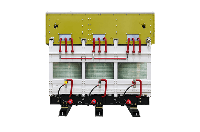
Four-Quadrant Phase-Shifting Rectifier Transformer
This multi-winding dry-type transformer supports a four-quadrant converter during motoring and regenerative braking. Split high-voltage windings and adjusted low-voltage winding geometry help control the impedance of each converter group, while the transformer, converter, protection, and grid interface are engineered as one bidirectional system.
- Rated voltageUp to 10 kV
- Rated capacityUp to 21 MVA
- DutyBidirectional converter duty
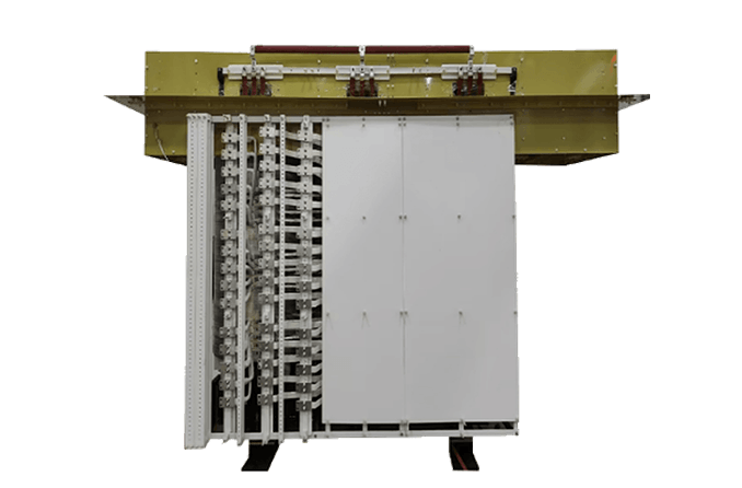
27,500 kVA & 24,300 kVA Phase-Shifting Rectifier Transformer
These large-capacity dry-type transformers use multi-winding phase shifting, continuous high-voltage winding structures, multiple low-voltage cooling ducts, forced-air ventilation, and transport reinforcement. The 27,500 kVA reference design serves a soft-start duty with a project-defined full-load duration and restart interval, so the duty cycle forms part of the transformer rating.
- Reference capacities24.3 MVA and 27.5 MVA
- Rated voltageUp to 35 kV
- Cooling and dutyForced-air, project-specific duty cycle
22kV / 35kV High-Voltage Multi-Winding Phase-Shifting Rectifier Transformer
This transformer connects directly to a 22 kV or 35 kV system and supplies multiple low-voltage outputs with controlled phase displacement. Continuous windings, increased insulation distances, electric-field control at winding ends, and ducted air cooling can be incorporated to address the higher insulation and thermal duty.
- Primary voltage22 kV or 35 kV
- Rated capacityUp to 20 MVA
- Winding arrangementMultiple phase-shifted secondary windings
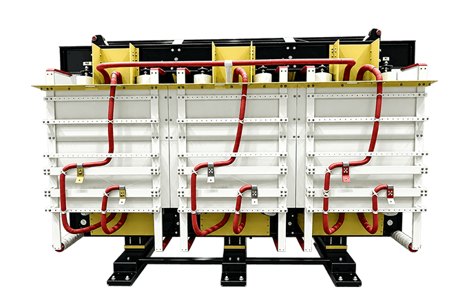
Phase-Shifting Rectifier Transformer for Medium Voltage Drive Systems
This multi-winding dry-type transformer supplies the rectifier front end of a medium voltage variable frequency drive. Delta or wye primary connections and independent low-voltage winding groups can be configured for the required phase displacement, voltage, impedance, and bridge arrangement.
- Rated voltageUp to 35 kV
- Rated capacityUp to 30 MVA
- CoolingAN or AF
Match the Transformer to the Power System
The application conditions below change winding currents, fault behavior, thermal duty, interfaces, or acceptance criteria even when transformers share the same medium-voltage rating.
Facility Distribution
The facility load profile determines how no-load and load losses contribute to annual operation. Vector group, grounding, taps, short-circuit level, protection, enclosure, and the acoustic target must match the downstream switchgear and loads.
Medium Voltage Drives and Rectifier Systems
The design must use the converter supplier’s bridge topology, harmonic-current spectrum, operating modes, overload profile, pulse number, winding-current distribution, and impedance targets. Final current distortion depends on the transformer phase displacement together with the converter, source impedance, loading, balance, and measurement point.
Heavy-Duty EV Charging
Charging capacity, DC bus voltage, rectifier arrangement, simultaneous charger demand, grid fault level, harmonic limits, and future expansion determine the winding groups and transformer rating. Protection and controls must coordinate the AC transformer with the charging rectifier modules.
Shore Power and Marine Systems
Shore power projects require coordination among the utility source, shore converter, isolation transformer, cable connection, vessel distribution system, and grounding method. Frequency, shore and vessel voltages, neutral treatment, converter harmonics, salt-laden air, humidity, corrosion, vibration, cooling-water availability, and the applicable marine approval route belong in the initial specification.
Regenerative Drives
Motoring, braking, reversing, and low-load profiles define the transformer’s bidirectional electrical and thermal duty. The design must maintain the specified impedance balance across these operating modes, while protection and metering recognize both power directions.
Specify the Electrical Requirements
Each item below changes a part of the electrical or mechanical design.
| Required input | Why it affects the transformer |
|---|---|
| Single-line diagram and system function | Establishes whether the unit provides distribution, isolation, phase shifting, converter duty, or a combination of functions. |
| Continuous and short-time kVA/MVA duty | Sets conductor current, thermal loading, cooling capacity, and mechanical forces. For a balanced three-phase system, apparent power is based on line voltage and line current; converter duty still requires the actual current waveform and overload cycle. |
| Primary and secondary voltages | Determines the turns ratio, insulation design, current on each winding, terminal arrangement, and compatible equipment voltage class. |
| Frequency and allowable voltage variation | Controls magnetic flux density and the available margin against overexcitation. A 50/60 Hz requirement must be stated during design. |
| Number of windings, vector group, and phase displacement | Defines grounding behavior, zero-sequence paths, rectifier pulse arrangement, and compatibility with parallel sources or converter bridges. |
| Taps and regulation requirement | Establishes the adjustment range and whether the transformer uses de-energized taps or another project-defined voltage-control method. |
| Impedance and available fault current | Changes downstream short-circuit current, voltage drop, protection coordination, converter commutation, and parallel load sharing. |
| Load type and harmonic spectrum | Determines additional winding and structural losses, hot-spot risk, neutral loading, winding-current balance, and the thermal verification method. |
| Insulation level and test requirements | Sets dielectric clearances, winding insulation, impulse and power-frequency withstand duties, partial-discharge criteria, and the acceptance test plan. |
| Grounding and shielding | Defines the neutral arrangement, fault-current path, protective bonding, and any electrostatic shield connection. |
| Terminals, bus, cable, and phase sequence | Determines the physical interface, clearances, flexible connections, and installation layout. |
| Applicable standards and evidence | Defines the design rules, test classifications, reports, certificates, and third-party or witnessed tests required by the contract. |
For parallel transformers, submit the required voltage ratio, vector group, phase sequence, impedance and tolerance, tap position, and operating arrangement for every unit. A capacity total alone cannot establish stable load sharing.
For converter duty, include normal load, low load, overload, bridge-out, regeneration, start-up, and grid-unbalance cases. These modes can change current sharing, losses, temperature rise, and harmonic performance even when the transformer nameplate capacity stays the same.
Send Electrical SpecificationsPlan Cooling, Enclosure, and Site Conditions
Dry-type transformers release winding and core losses into the surrounding cooling system. The available air path, allowable temperature rise, enclosure restriction, altitude, ambient temperature, and load cycle determine whether natural air, forced air, or AFWF cooling is appropriate.
Natural Air and Forced Air
Natural-air cooling uses buoyancy-driven airflow through designed winding and core passages. It avoids powered fans during base operation, but the room and enclosure must provide the required inlet area, outlet area, clearances, and heat rejection. Dust accumulation, blocked louvers, recirculated hot air, and restricted installation spacing reduce cooling performance.
Forced-air cooling adds fans to move more air through the active part. The specification must define the self-cooled and fan-cooled ratings, fan supply, control stages, alarm and trip logic, redundancy requirement, filter arrangement, and acoustic condition. Fan operation changes both available capacity and sound level.
AFWF Closed-Loop Cooling
AFWF cooling circulates internal air through the transformer and an air-to-water heat exchanger. This arrangement reduces continuous exchange with contaminated external air and can support a high heat load inside an IP54 enclosure. The design still depends on cooling-water inlet temperature, flow, quality, pressure, fouling allowance, condensation control, pumps, leak detection, alarms, and loss-of-water behavior.
Environmental and Installation Inputs
- Altitude: Lower air density reduces dielectric and cooling performance, so a high-altitude site can require revised clearances, insulation coordination, cooling, or rating.
- Ambient temperature: Maximum, daily average, annual average, and minimum temperatures affect the thermal design and material selection.
- Dust and conductive particles: Open ventilated windings require clean airflow and planned inspection. A protected enclosure or closed cooling circuit may be necessary when contaminants cannot be controlled.
- Humidity, condensation, salt spray, and corrosive gases: Specify the actual exposure, test or coating requirement, heater strategy, enclosure, materials, and maintenance plan.
- Indoor or outdoor location: Outdoor duty requires project-defined weather protection, solar-load consideration, drainage, corrosion protection, seals, and ventilation.
- Space and access: Provide room dimensions, transportation route, lifting limits, floor loading, cable approach, maintenance clearance, and maximum equipment envelope before the mechanical design is frozen.
- Noise and vibration: State the measurement condition, cooling state, distance, and site limit. Fans, pumps, structure-borne vibration, and the transformer core contribute through different paths.
Manufacturing and Factory Test Scope
The winding insulation process must match the approved construction: resin casting for cast-resin units or impregnation and curing for VPI and non-encapsulated units. AFWF and forced-air designs add fans, pumps, sensors, alarms, trips, and cooling controls to the functional acceptance scope.
The approved inspection and test plan should identify the governing standard, transformer type, contractual guarantees, test classification, witness points, instruments, reference temperatures, tolerances, and report format before testing begins.
Typical Completed-Unit Checks
- Winding resistance at the stated temperature and tap positions
- Voltage ratio, polarity, phase displacement, and vector group
- No-load loss and no-load current at the specified voltage and frequency
- Load loss and short-circuit impedance at the defined reference temperature
- Insulation resistance and the specified dielectric withstand tests
- Partial-discharge measurement with the applied-voltage sequence and acceptance criterion recorded
- Functional checks for fans, pumps, temperature sensors, alarms, trips, and control interfaces
- Nameplate, terminals, phase sequence, dimensions, accessories, drawings, and packing-document verification
A rectifier transformer requires additional verification of every secondary phase group, the defined multi-winding impedance combinations, and the winding-current arrangement. Transformer factory tests establish the condition and performance of the unit under the agreed test method. Converter current sharing, DC output, regenerative operation, protection coordination, and harmonic limits require system-level commissioning with the associated power electronics and grid conditions.
Discuss a Test PlanTell Us About Your Project
- Phone: 8615267082061
- Email: [email protected]
- WhatsApp: 8615267082061
- Address: 333 Minta Road, Songjiang District, Shanghai