 BBELC
BBELC
Distribution Transformer Connections & Winding Rules
47Master Distribution Transformer Winding Connections. Discover Core Rules, Vector Groups, And The Zero-Fault Framework.
View details
Search the whole station
2026 Edition 33/6.6kV Buck and Voltage Transformer Project Procurement Pit Avoidance and Practical Operation Manual
In the industrial and power system, 33/6.6kV transformer is absolutely indispensable “heart” node. It is either used as a step-down transformer to reduce the transmission voltage of 33kV to 6.6kV to supply power to large industrial motors and mining equipment. Or it can be used as a step-up transformer to pull up the 6.6kV power generated by wind power, photovoltaic and other new energy power stations to 33kV and then merge it into the power grid.
But the reality is very skinny: in today’s international trade, more than 60% of purchasing veterans are still copying the old technical specifications of 2015 when issuing bids. The direct consequence of this serious disconnect is that many newly bought transformers, 1 to the toss of those non-linear loads in modern industry, can not even last half of their expected life. In order to help engineers and the general contractor completely avoid these procurement pits, we have specially compiled this set of technical dismantling and procurement matrix.
2026 Technical Baseline: Why is the traditional 33/6.6kV technical specification not working well?
The update speed of the transformer industry standard is much faster than most purchases to refresh the Word template. By 2026, the global distribution transformer market has long written “ultra-low empty load loss” and “mandatory use of environmentally friendly insulation fluid” into hard regulations.
Traditional mineral insulating oil is facing extremely stringent environmental requirements. Both the EU’s EcoDesign Tier 2 standard and the current energy efficiency regulations of the US Department of Energy (DOE) are forcing manufacturers to use high-quality cold-rolled oriented silicon steel (CRGO) to minimize iron loss. At present, when drafting the tender documents for the 33/6.6kV system, the MV electrical engineer must write clearly in black and white: natural ester (vegetable oil) is required as the insulating medium. You know, the ignition point of this thing is as high as 360 ℃, far exceeding the limit of 160 ℃ of mineral oil. Switching to vegetable oil can not only fill up the safety factor, but also save the trouble of building expensive concrete firewalls, directly reducing the floor area of the substation by as much as 15%.
| Comparison Metric | 2020 Standards (Baseline) | 2026 Mandates (Upcoming Requirements) | Key Differences & Impact |
| Iron / Copper Loss Limits | Standard Efficiency (e.g., EU Tier 1/2 or IEEE equivalent)• Iron Loss (No-Load): Standard grain-oriented silicon steel limits.• Copper Loss (Load): Baseline limits deemed acceptable for standard distribution. | Ultra-High Efficiency Mandates (Tier 3 equivalent)• Iron Loss: Strict reduction (approx. 10-20% lower). May require amorphous core technology.• Copper Loss: Strict limits forcing larger conductor cross-sections. | Impact: 2026 units will have a higher upfront CAPEX (heavier/larger cores) but significantly lower OPEX and carbon footprint over the asset lifecycle. |
| Dielectric Fire Point | Class O Fluids (Conventional)• Predominantly standard mineral insulating oil.• Fire Point: ≥ 170°C (Standard).• Clearance: Requires standard firewall and blast clearance parameters. | Class K Fluids (Less-Flammable / Green)• Mandatory use of natural or synthetic ester fluids (e.g., FR3, Midel).• Fire Point: ≥ 300°C.• Clearance: Reduced spatial clearance allowed. | Impact: Substantial improvement in substation fire safety and environmental compliance (ESG). Ester fluids are also fully biodegradable. |
| SCADA Interface Requirements | Basic & Hardwired Analog• Interface: Hardwired analog (4-20mA) and dry contacts.• Protocols: Modbus RTU or basic DNP3 via serial.• Monitoring: Basic OTI/WTI (Oil/Winding Temp) and Buchholz relay status. | Advanced Digital & IoT Integration• Interface: Native fiber-optic / Ethernet ports.• Protocols: IEC 61850 (GOOSE messaging) / DNP3 over TCP/IP.• Monitoring: Built-in predictive maintenance, online DGA (Dissolved Gas Analysis), and cybersecurity compliance. | Impact: 2026 mandates shift transformers from passive assets to “Smart Nodes,” requiring advanced cybersecurity and enabling predictive condition-based maintenance. |
If you copy the parameters on the nameplate of the competition with your eyes closed, you will often end up either delaying the commissioning or being rejected directly by the power grid. At present, the head electrical contractors are using a set of “VIP selection matrix” to accurately determine the various indicators of 33/6.6kV transformers.
How to configure the on-load voltage regulating tap changer directly determines the long-term power supply reliability of the equipment. In many places, it is common for the 33kV power grid to have a voltage drop of about 10% from 1 to peak power consumption. Therefore, in the procurement documents, do not choose non-excitation voltage regulation (OCTC) in order to save some money, and must stick to on-load voltage regulation (OLTC). With automatic voltage regulator (AVR), OLTC can keep the voltage fluctuation on the 6.6kV side within a very narrow range of +/-1.5 under the condition of no power supply.
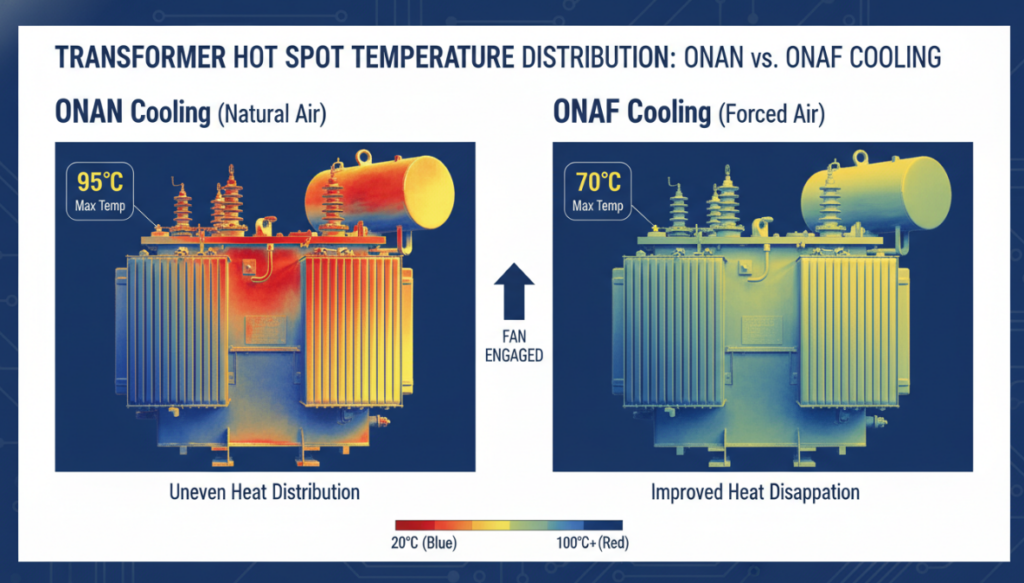
The heat dissipation requirements of heavy industry are completely different from those of the municipal power grid. If only a standard ONAN (oil-immersed self-cooling) cooling system is equipped, continuous full-load operation in summer will be terrible, not to mention 120% overload. The buyer must add the ONAF (oil-immersed air-cooled) expansion interface to the initial inquiry sheet (RFQ) and indicate that the manufacturer’s own automatic fan controller must be connected in advance. Infrared thermal imaging measurements have long proved that after the ONAF cooling system is turned on, a transformer rated at 10 MVA can stably output 12.5 MVA even at extreme high temperatures. With this scalable cooling solution, you can save about 18% of your initial investment compared to buying a machine 12.5 MVA directly.
Heavy industry is most afraid of unplanned downtime, and gas relay (Buchholz) misoperation often causes heavy downtime losses. A smart transformer that meets the 2026 standard must be directly embedded in the hottest point of the winding when the fiber grating sensor is assembled at the factory. This direct measurement of temperature at the physical level completely eliminates the previous backward algorithm of “guessing” the winding temperature by the top oil temperature. With it, the SCADA system can receive millisecond-level overheating alarms and take the initiative to unload in advance before the transformer is really burned out by high temperature.
Step-down transformer: watch out for high-order harmonics to scrap equipment
From high pressure to low pressure, it is often a high incidence area of load end failure. Many purchasing managers buy step-down transformers regardless of what equipment is used in downstream factories.
Now the industrial park is full of high-power frequency converter (VFD) and electric arc furnace. These guys will unceremoniously pour the violent 3rd, 5th and 7th harmonics back into the 6.6kV bus. Harmonics force transformer windings to experience pronounced skin effect and eddy-current losses. If an ordinary step-down transformer is thrown into a heavy inverter environment, its insulation paper will be absolutely carbonized within 3 years (36 months). If the non-linear load in the park exceeds 30%, the design engineer must specify the K-13 coefficient rating in the tender, or require the installation of an internal electrostatic shielding layer to physically block high-frequency interference from the door.
Distributed energy sources such as photovoltaic power plants and wind farms have extremely abnormal requirements for transient shock resistance on the grid side. The step-up transformer has to push the 6.6kV generated by the generator into the 33kV transmission network. Its daily routine is endless start-stop cycle and serious voltage swell.
The severe rate of voltage change (dv/dt) generated by large-scale photovoltaic inverters can severely degrade the turn‑to‑turn insulation on the 6.6kV low‑voltage side. Therefore, the coil winding process must use thick kraft paper insulation on the copper wire and add a sacrificial buffer layer at both ends of the coil. Recently, a 20MW grid-connected project in Texas has given a bloody lesson: a step-up transformer without end insulation reinforcement has only experienced 50 reclosings, and the partial discharge (PD) data has directly soared by 400, and insulation breakdown is imminent.
To be honest, the parameters on the nameplate cannot be fully believed. The only reliable way to control the quality of the transformer is to keep an eye on the factory acceptance test (FAT). Take last year as an example. We checked and accepted a batch of 33/6.6kV transformers for a large multinational mining enterprise. At that time, we stopped production directly at the workshop site.
At that time, the engineer in charge of the temperature rise test found that the temperature rise of the top oil was barely on the pass line of 60K, but the data of winding resistance was 1 calculated. Boy, the internal hot spots had already crossed the red line stipulated by IEC. After careful 1, it was found that the supplier had secretly cut off the external heat sink by 15% in order to save money. We called for a shutdown on the spot, forcing them to redesign the cooling system and redo the test 1 times until it was fully compliant with IEC 60076-2. Therefore, overseas buyers must not be superstitious about big names or just look at PDF reports sent by manufacturers. A third party must be invited to supervise the manufacture and stare at the oscilloscope waveform and temperature rise curve at FAT site.
Dyn11 is definitely the first choice, which is also the industry standard. The corner connection (D) on the 33kV high-voltage side is like a cage, which can deadlock the third harmonic current and prevent them from running into the power grid to cause damage. The 6.6kV low-voltage side of the star (Y) can provide a very stable neutral point, which is very critical for industrial motors to achieve accurate ground fault protection.
In theory, it is true that electricity can be supplied, but in actual engineering, it is purely for oneself to find no fun. The dedicated step-up transformer is specially designed on the short-circuit impedance and the low-voltage (generator) side insulation, which is designed to withstand the operating overvoltage. If you force the ordinary step-down transformer to reverse power transmission, the closing inrush current will be very large, then your relay protection will trip by mistake every day, and you will have a headache.
According to the 2026 high energy efficiency standard, the iron loss (no-load loss) of this specification should be stuck between 3.5 kW and 4.2 kW. If the no-load loss on the test report is over 5.0 kW, don’t even think about it. The manufacturer definitely cut corners on the silicon steel sheet and used degraded inferior materials. If this pit is stepped on, thousands of dollars of electricity will be wasted every year.
It depends on the load in your factory. If the peak power consumption does not exceed 80% of the rated capacity of the transformer, ONAN self-cooling is completely enough. But if you plan to expand production in the next three years, or if the seasonal load peak is approaching 100 percent, don’t hesitate to go straight to ONAF. Adding a few more sets of fans does not add much hard cost at all, but it is equivalent to picking up about 25% of the capacity increase in vain, and calculating absolute blood earnings from the economic account.
Oil chromatography (DGA) is definitely your “life-saving stunt”. The maintenance team has to take oil samples at least once a year, focusing on the indicators of hydrogen, methane and acetylene. Do remember: as long as you see even a little bit of “acetylene” concentration, the basic hammer inside the transformer arc discharge. At this time, the power is cut off quickly and the hanging core is ready for inspection. If the transformer is on fire and you still dare to run with electricity, then basically wait for it to explode in situ.
Master Distribution Transformer Winding Connections. Discover Core Rules, Vector Groups, And The Zero-Fault Framework.
View detailsThe working principle of the line isolation transformer is actually very simple: it converts electrical energy into a magnetic field, and then back into electrical energy. In this simple step, the input power supply and output load are completel...
View detailsDiscover How Modular Platforms Replace Pure Custom Large Transformers To Cut Delivery Time By 40%.
View detailsSource From An OEM China Pad-Mounted Distribution Transformers Factory To Bypass Middlemen And Prevent Grid Failures.
View detailsPlease fill in the arithmetic result.
The calculation is incorrect, please fill it in again.