 BBELC
BBELC
Power Supply Transformer Function: What Is It Used For
58Discover Power Supply Transformer Function: What Is It Used For? Master SMPS Designs And Prevent Circuit Failures.
View details
Search the whole station
The winding connection mode of the distribution transformer directly determines how the primary and secondary coils cooperate to set the voltage level, generate phase difference, and deal with the troublesome harmonic problems. There is an iron law in the field construction: the connection group of transformers must be closely matched with the phase requirements of the power grid. Even if it is only the wrong 1 phase, it will directly cause a devastating short-circuit accident at the moment of grid-connected operation.
We went through more than 500 debugging accident reports and pulled out the real culprit behind these failures. The following is to give you a detailed dismantling, a line of engineers is how to ensure that the distribution transformer wiring “zero error.
Different power grid structures have to be matched with different winding schemes. Engineers mainly look at three points: how to deal with ground faults, zero sequence impedance, and whether it can suppress harmonic currents.
For commercial and industrial loads, the combination of primary triangle (Delta) and secondary star (Wye) is the most reliable choice. Why? Because the primary winding of the triangle is like a physical blocking circle, trapping the multiples of 3 harmonics (such as the third harmonic) in the closed loop to prevent these “dirty things” from polluting the upstream high-voltage transmission lines. At the same time, the star connection on the secondary side can lead to a very stable neutral point, so that the system can drive the three-phase motor while supplying power to the single-phase lighting without delay.
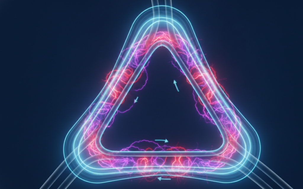
Y-Y connection has a congenital flaw: it does not have a closed loop to discharge zero-sequence current. Now the distributed energy source (DER) of solar farm is connected in large quantities, and a large amount of harmonics are poured into the power grid. The hard injury of Y-Y connection is infinitely magnified. If there is no circuit to let the harmonics flow, once an asymmetric fault occurs, the neutral point will produce a serious offset, causing the voltage of the healthy phase to soar instantly. In order to cover the bottom, the grid designer can only bury a third winding (usually triangular connection) in it. This third coil is usually unloaded, purely to provide a circulating channel for the zero sequence current, thus stabilizing the neutral point.
| Vector Group | Typical Application | Harmonic Handling | Grounding Type |
| Dyn11 | Common distribution transformers feeding low-voltage commercial/residential grids (unbalanced loads). | Excellent. The primary delta (ΔΔ) winding traps and circulates 3rd harmonic currents, preventing them from injecting into the HV grid. | Secondary neutral (nn) is available and can be solidly grounded or grounded through low impedance. |
| Yyn0 | Medium-voltage distribution or auxiliary transformers with balanced, symmetric loads. | Poor. 3rd harmonic currents cannot flow on either side due to the star connections without neutral paths, which may cause voltage waveform distortion. | Both HV and LV neutrals can be grounded, though LV unbalance capability is limited. |
| Ynd11 | Step-up transformers at generating stations or high-voltage substation step-down transformers. | Good. The delta (ΔΔ) winding on the secondary side provides a closed path for 3rd harmonic currents to circulate. | HV Star neutral (YY) can be solidly grounded; LV Delta side requires a grounding transformer (zigzag) if system grounding is needed. |
| Yzn11 | Distribution systems with highly unbalanced loads or industrial applications with severe phase imbalances. | Very Good. The zigzag (zz) connection on the secondary side cancels out zero-sequence magnetic flux, mitigating 3rd harmonics. | Secondary neutral (nn) can be solidly grounded and can handle 100% of the rated current of unbalanced neutral loads. |
| Dd0 | Industrial plants, isolation transformers, or systems where no neutral reference is required on either side. | Excellent. Both delta windings circulate and contain triple-harmonic currents within the windings. | Ungrounded on both sides. If grounding is required, an external grounding transformer (zigzag) must be installed. |
Field technicians face immense pressure during substation energization. We developed the P.A.C.T. framework to eliminate guesswork during distribution transformers connections.
Subtractive polarity is the IEEE standard for distribution transformers above 200 kVA and high voltages above 8,660V. Additive polarity applies to smaller units. Technicians must conduct a DC kick test. Reversing the H1 and X1 terminal relationships instantly creates a dead short when integrated into a three-phase bank.
Phase displacement is non-negotiable. A Dyn11 transformer leads the primary voltage by 30 degrees. A Dyn1 lags by 30 degrees. You cannot force them to work together. Verify the nameplate vector group against the substation single-line diagram before bolting any lugs.
Solidly grounded, resistance grounded, or ungrounded. The Wye secondary neutral requires a specific grounding mechanism based on the facility’s fault clearing time. Drive the ground rod impedance below 5 ohms for solid setups to ensure rapid breaker tripping during a line-to-ground fault.
Never energize based on visual inspection alone. Execute a Transformer Turns Ratio test across all tap changer positions. Follow this with a Megger test between primary, secondary, and ground.
The threshold for transformers to operate in parallel is high: voltage ratio, impedance and connection group must be divided into no different parts. But there are some inexperienced construction teams who don’t take the connection group seriously at all.
In a documented industrial commissioning incident in 2023, an outsourced team attempted to connect an old Dyn1 transformer and a newly installed Dyn11 transformer in parallel. Coincidentally, the voltage levels and impedance percentages of the two machines are exactly the same. As a result, the technician just closed the female circuit breaker ——the system reacted violently within 40 milliseconds and tripped the original side relay directly.
What is the reality? Dyn11 produces a phase shift of +30°, while Dyn1 is -30°. In terms of inside and outside, there is a full 60 degrees difference between the two. Hardening two power supplies that differ by 60 degrees together will produce an extremely terrifying circulation, with the power equivalent to a severe metallic phase-to-phase short circuit. That accident directly caused serious damage to equipment on site. Lesson learned: Never switch to a female connection without first measuring the phase angle with a power quality analyzer.
A: If you reverse the Δ-Y transformer used for step-down, the entire physical characteristics of the ground are completely changed. The new secondary side (the side of the original triangle) loses its neutral reference to direct ground, and the system becomes an ungrounded system. At this time, you must immediately install a Z-type grounding transformer (tortuous transformer), otherwise the system will not be aware of the ground fault.
Answer: Yes. Both wiring methods produce a phase difference of +30 degrees between the primary and secondary terminals. As long as their voltage ratio and impedance scale unitarity match (the error is controlled within 10%), they can obediently share the load proportionally and will not generate fatal circulation.
Answer: The pole reduction performance effectively reduces the voltage stress between adjacent primary and secondary side coils when the equipment is running. To put it bluntly, if the sleeves on one or two sides are accidentally short-circuited and overlapped one day, the voltage between the two will be decreasing (difference) rather than adding, which can greatly reduce the catastrophic risk of insulation breakdown.
A: Z-winding is mainly used to create a rigid “neutral point” for ungrounded electrical systems. It has a unique skill: for normal symmetrical three-phase current, it exhibits extremely high impedance and basically does not affect operation; but when encountering a ground fault, its zero-sequence impedance becomes particularly low, allowing the fault current to flow smoothly back to the relay to trigger tripping.
A: Devices like solar inverters will reverse the power back to the distribution transformer. If the transformer is connected to a star ground, this power flow back will cause severe transient overvoltage on the mains line when the grid is disconnected. Therefore, power companies now force the use of specific grounding strategies (such as grounding the original edge without grounding) to block this zero-sequence reverse power supply to the dead.

Discover Power Supply Transformer Function: What Is It Used For? Master SMPS Designs And Prevent Circuit Failures.
View details
Optimize Reactive Power Transformer Core Capacity And Load Control To Manage Reactive Power Of Transformer For Grid.
View details
Whether and how to ground the neutral point of a power transformer is a problem that many people encounter when they first come into contact with a substation or distribution system. In Chinese, it says that the neutral point is grounded. The corr...
View details
A power transformer may appear to be a quiet unit, but structurally, its typical components include a magnetic core, primary and secondary windings, main insulation, leads and terminals, tap-in components, housing or fuel tank, cooling structure, ...
View detailsPlease fill in the arithmetic result.
The calculation is incorrect, please fill it in again.