
 BBELC

Power Transformer Manufacturer
BBELC designs and manufactures dry-type power transformers and special transformer systems for medium-voltage drives, multi-pulse rectifiers, data centers, renewable energy, marine power, and industrial conversion equipment. Electrical ratings, winding arrangements, cooling, enclosure, and mechanical interfaces are coordinated around the actual power system and operating duty.
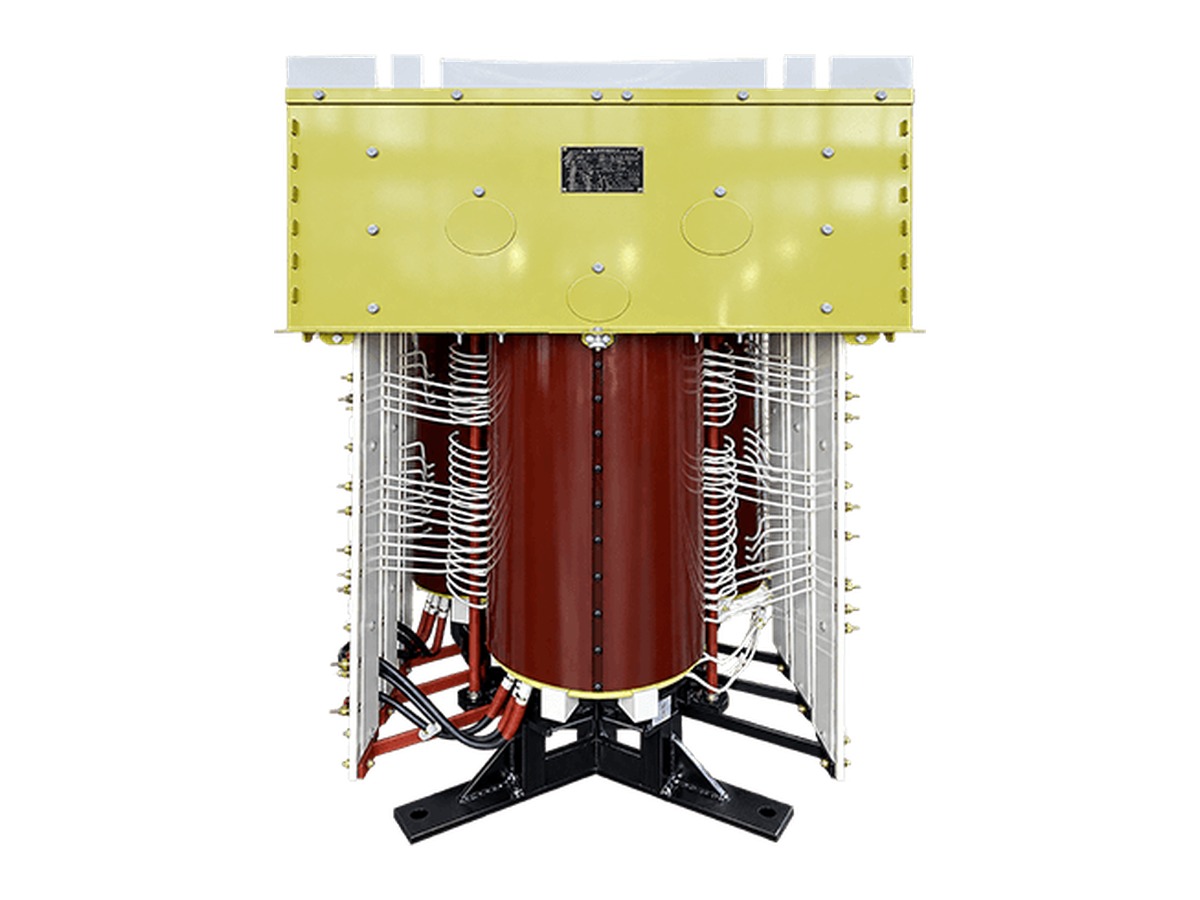
Power Transformer Project
A BBELC delta-core transformer configured for multi-winding phase-shifting duty in an industrial power-conversion system.
Power Transformer Platforms for Conversion and Distribution
BBELC manufactures transformers for voltage conversion, electrical isolation, power distribution, and converter duty. The range includes general and compact phase-shifting rectifier transformers, four-quadrant designs for regenerative drives, 22 kV and 35 kV multi-winding units, data center transformers, high-capacity dry-type products, renewable-energy transformers, marine and shore-power transformers, and application-specific isolation transformers.
The product architecture follows the system task. A phase-shifting rectifier transformer supplies multiple secondary voltages with controlled phase relationships for a multi-pulse rectifier. A four-quadrant unit supports a converter that operates during motoring and regenerative braking. A delta-core arrangement reduces equipment width where the installation envelope is constrained. Data center designs interface with HVDC, 240 V or 336 V DC architectures, modular rectifiers, or UPS front ends.
Dry-type construction can use natural air, forced air, or a closed air-to-water cooling circuit. Insulation may use Class F or Class H materials, with impregnation or cast-resin construction selected for the product and environment. Choose the platform by system function first: distribution or isolation, rectifier duty, regenerative operation, high-voltage input, a restricted footprint, or closed-loop cooling.
Compare Product PlatformsDefine the System Before Choosing the Transformer
A suitable transformer begins with the power path. Identify the normal and reverse power-flow directions, primary and secondary voltage ranges, frequency, grounding method, system fault level, and allowable voltage variation. These inputs determine the ratio, connection group, insulation coordination, tap arrangement, and protection interface.
The load defines the electrical and thermal duty. For a rectifier or drive, provide the bridge topology, pulse number, phase-shift requirement, DC operating range, current waveform, harmonic spectrum, overload cycle, starting duty, regeneration, and required winding impedance balance. A nameplate kW total cannot represent additional winding loss, intermittent peaks, bridge imbalance, or bidirectional operation.
The installation determines cooling and mechanical construction. Ambient temperature, altitude, humidity, condensation, dust, corrosive exposure, ventilation, noise limits, enclosure protection, available footprint, lifting route, and terminal access affect temperature rise, clearances, airflow, materials, dimensions, and maintenance space.
The acceptance plan completes the specification. State the governing standard and version, guaranteed values, routine and special tests, witness points, report format, drawing requirements, destination, and packing constraints before design release.
Send Your Electrical SpecificationsFeatured Power Transformer Products
Delta-Core Phase-Shifting Rectifier Transformer
The open delta-stacked core and phase-shifting windings reduce transformer width for skids, containers, and equipment rooms with a restricted installation envelope. The design provides voltage conversion, isolation, and controlled phase displacement for medium-voltage drive and rectifier systems.
- Rated voltageUp to 10 kV
- Rated capacityUp to 4 MVA
- Insulation classF or H
- Design standardsIEC / IEEE as specified for the project
Four-Quadrant Phase-Shifting Rectifier Transformer
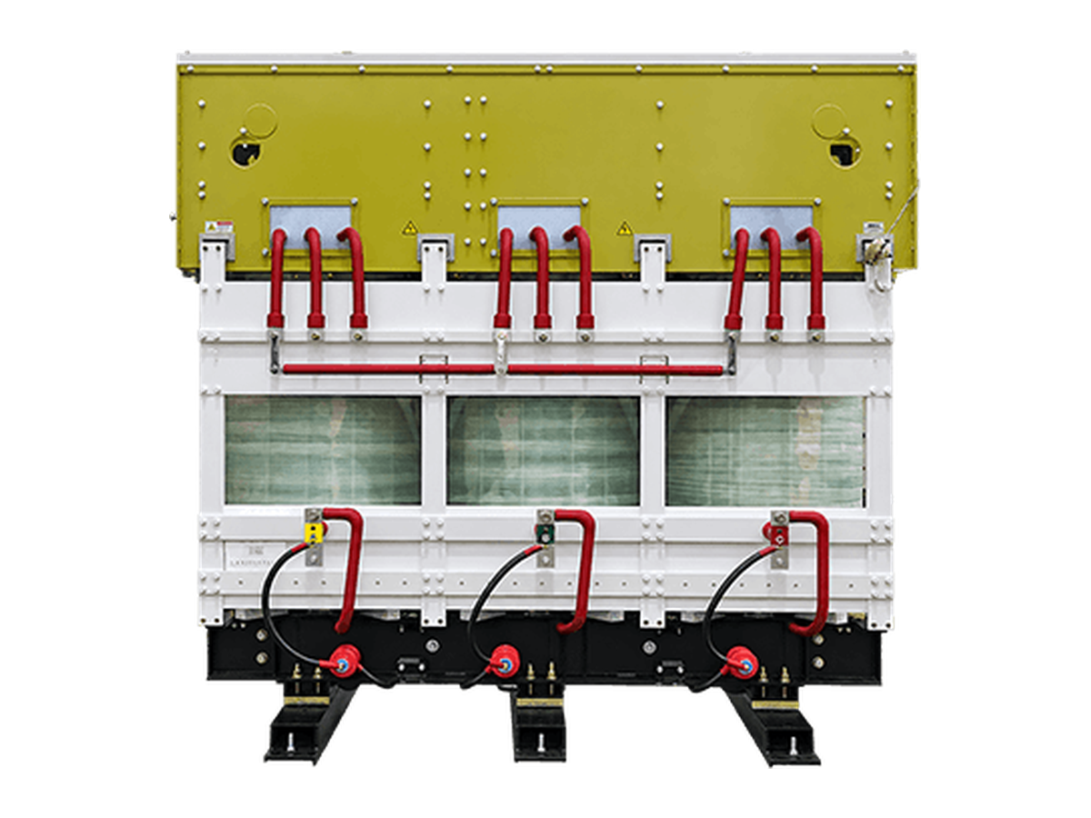
This multi-winding dry-type transformer supports converters with bidirectional power flow. Split high-voltage windings and adjusted low-voltage winding geometry help control group impedance for mine hoists, cranes, propulsion, test platforms, and other drives that return braking energy to the grid.
- Rated voltageUp to 10 kV
- Rated capacityUp to 21 MVA
- Insulation classF or H
- DutyMotoring and regenerative converter operation
27,500 kVA & 24,300 kVA Phase-Shifting Rectifier Transformer
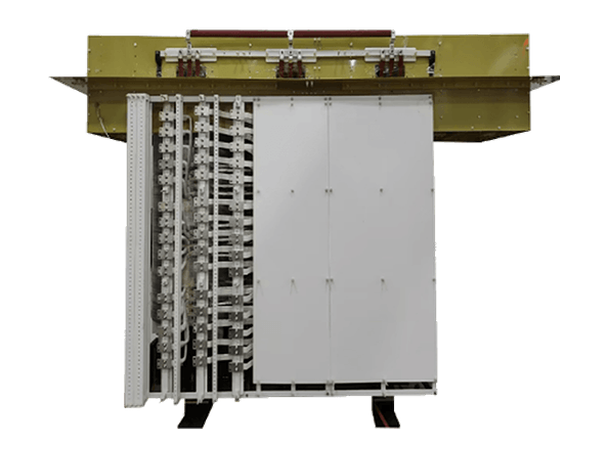
These large-capacity dry-type platforms use multi-winding phase shifting, continuous high-voltage winding structures, multiple low-voltage cooling ducts, forced-air ventilation, and transport reinforcement. The 27,500 kVA reference design serves a soft-start duty, so full-load duration and restart intervals form part of the rating rather than a separate operating note.
- Reference capacities24.3 MVA and 27.5 MVA
- Rated voltageUp to 35 kV
- CoolingForced air
- Operating dutyDefined for the project load cycle
22kV / 35kV High-Voltage Multi-Winding Phase-Shifting Rectifier Transformer
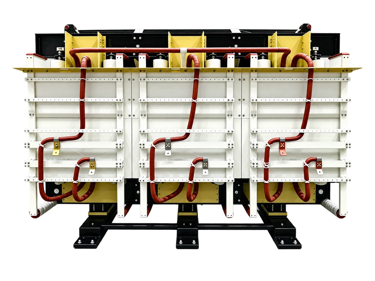
This transformer connects directly to a 22 kV or 35 kV system and supplies multiple low-voltage outputs with controlled phase displacement. Continuous windings, increased insulation distances, winding-end electric-field control, and ducted air cooling address the higher dielectric and thermal duty in large rectifier, renewable-energy test, rail-traction, and laboratory systems.
- Primary voltage22 kV or 35 kV
- Rated capacityUp to 20 MVA
- Secondary configurationMultiple phase-shifted winding groups
- ConstructionHigh-voltage dry-type rectifier transformer
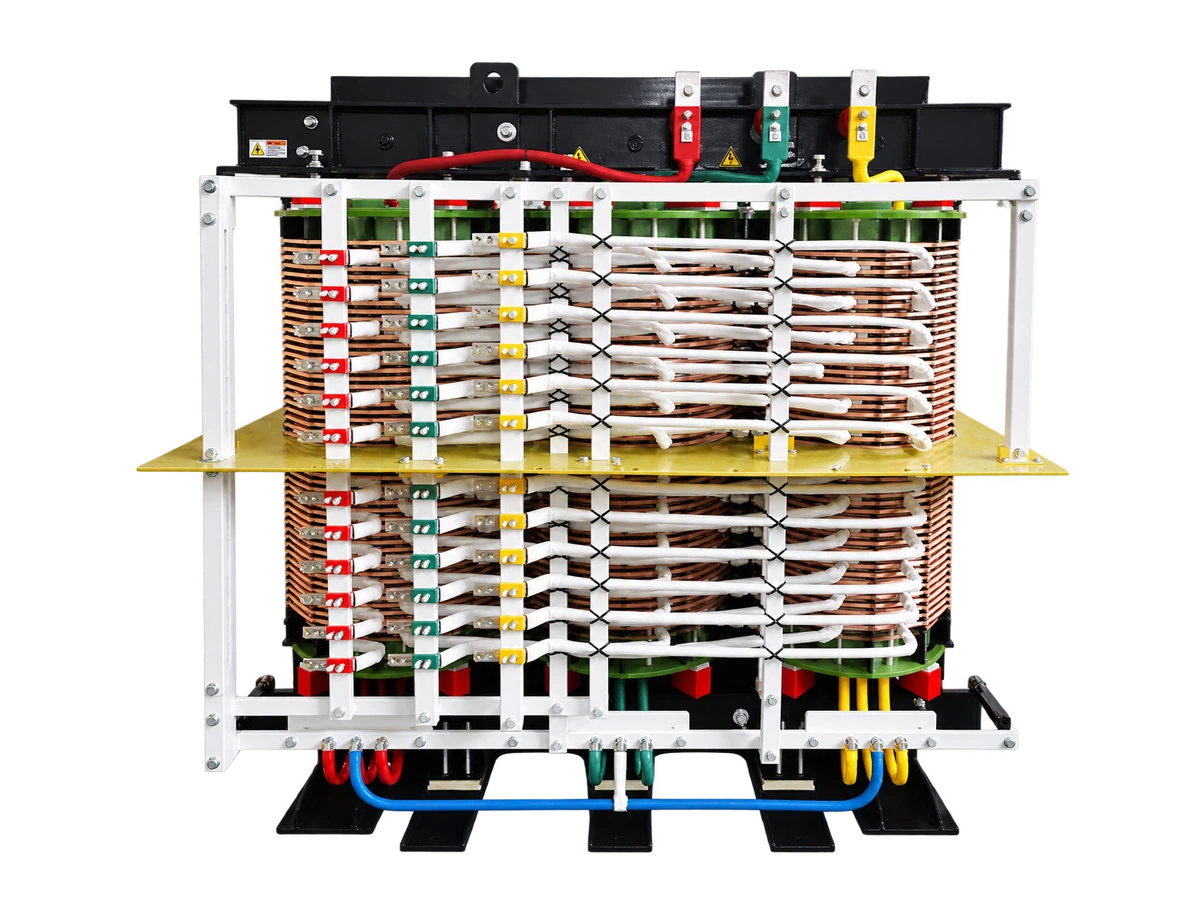
Phase-Shifting Rectifier Transformer for Data Center Power Systems
This dry-type transformer supplies HVDC systems, 240 V or 336 V DC architectures, modular rectifier groups, and high-efficiency UPS front ends. Independent winding groups can feed multiple rectifier modules while the phase arrangement supports multi-pulse conversion and cleaner interaction with the upstream AC system.
- Rated voltageUp to 10 kV
- Rated capacityUp to 3,100 kVA
- Insulation classF or H
- ApplicationsData center HVDC, modular rectifiers, and UPS front ends
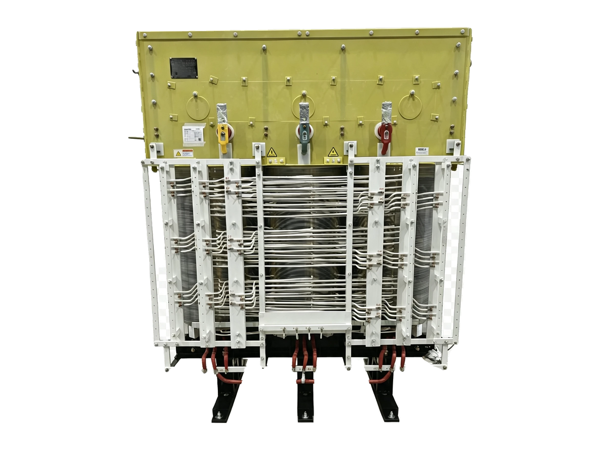
Phase-Shifting Rectifier Transformer for Medium Voltage Drive Systems
This multi-winding dry-type transformer supplies the rectifier front end of a medium-voltage variable-frequency drive. Delta or wye primary connections and independent low-voltage winding groups can be configured for the required phase displacement, voltage, bridge arrangement, and impedance.
- Rated voltageUp to 35 kV
- Rated capacityUp to 30 MVA
- Insulation classF or H
- CoolingNatural air or forced air
Engineering the Transformer Around the Power-Conversion System
The transformer and converter operate as one electrical system. BBELC coordinates secondary winding count, vector relationships, phase displacement, bridge loading, and winding-current balance with the converter topology. Twelve-pulse systems require two compatible secondary groups with the specified 30-degree displacement; higher-pulse systems require the transformer and converter teams to agree on phasors, group numbering, phase sequence, protection, and operating modes.
Impedance affects fault current, voltage drop, commutation, and current sharing at the same time. BBELC can adjust split high-voltage structures and low-voltage winding geometry for multi-group designs, then align the target impedance and tolerances with the converter supplier. Regenerative and bridge-out modes are included when they change current distribution or thermal loading.
Insulation and cooling are developed around voltage class, altitude, environment, load waveform, and enclosure. Available configurations include Class F or H insulation, natural- or forced-air cooling, and a closed AFWF arrangement in which internal air transfers heat through an air-to-water heat exchanger inside an IP54 enclosure.
Mechanical design covers terminals, bus or cable interfaces, phase sequence, footprint, lifting, transport, and service access. BBELC uses automated design tools, SolidWorks PDM and MBD 3D, while PLM, ERP, MES, and QMS connect approved engineering data with purchasing, manufacturing, quality, inventory, and order execution.
Discuss the System InterfaceControlled Manufacturing from Materials to Final Assembly
Manufacturing begins with contract review and the approved design. Incoming electromagnetic wire, insulation paper, insulation materials, varnish, grain-oriented silicon steel, and clamping components pass incoming inspection before release to production.
Coil production includes conductor insulation, winding, welding, in-process inspection, impregnation, and curing. Conductor paper wrapping is controlled as a special process, and coil welding is controlled as a key process. The insulation route follows the approved construction: Class H non-encapsulated windings can use NOMEX turn insulation, while other designs may use vacuum-pressure impregnation or cast-resin processing.
Core production covers silicon-steel inspection, slitting, cross-cutting, stacking, and semi-finished core inspection. Separately manufactured coils, insulation parts, leads, and core assemblies then pass component checks before final transformer assembly, completed-unit testing, outgoing quality inspection, and packing.
Review Manufacturing CapabilitiesFactory Tests Linked to the Delivered Transformer
Completed-unit testing verifies the transformer against its approved electrical design. The agreed test plan can cover visual checks, insulation resistance, winding resistance, voltage ratio, vector group and phase displacement, short-circuit impedance, load loss, no-load current, no-load loss, efficiency, applied and induced withstand tests, and partial-discharge measurement.
Multi-winding rectifier transformers require each secondary phase group and the specified impedance combinations to be checked. Test records identify the delivered unit and preserve the relevant values, conditions, tap positions, reference temperatures, instruments, and acceptance criteria.
Transformer factory tests establish the unit’s electrical condition and performance under the agreed method. Converter current sharing, DC output, harmonic limits, regenerative operation, protection coordination, alarms, and interlocks are verified during system commissioning with the associated power electronics and site network.
Define the Inspection and Test PlanTechnical Clarification, Design Release, and Handover Records
Technical clarification turns the agreed system duty and project boundaries into a design basis. The project-specific offer identifies the proposed transformer configuration and the open technical decisions that must be resolved before the design can be released.
The design review establishes the approved electrical and mechanical interface. Depending on the agreed scope, the review package can include the transformer data sheet, outline and interface drawings, terminal arrangement, and cooling and control requirements. Customer comments enter controlled revisions, and manufacturing uses the released version. A later change is evaluated against the electrical design, dimensions, materials, schedule, and test scope before a new revision is issued.
The handover package connects the approved design with the delivered unit. Agreed test reports record the measured results and test conditions, while released drawings, packing records, and other contract documents provide the reference for receiving, installation, and project records.
Start the Technical ClarificationDiscuss Your Transformer Project
- Phone: 8615267082061
- Email: [email protected]
- WhatsApp: 8615267082061
- Address: 333 Minta Road, Songjiang District, Shanghai