
 BBELC

Power Transformer Repair: Scope, Tests, and Decisions
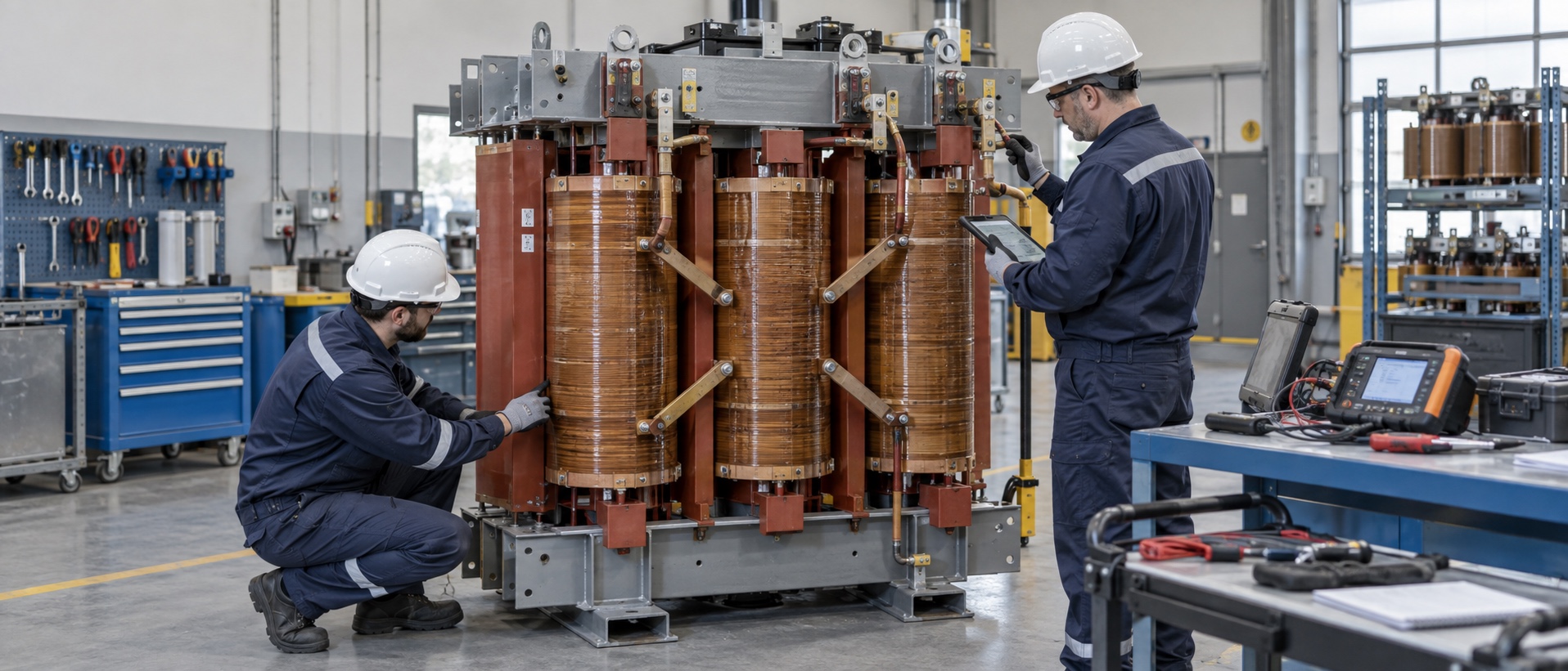
It is impossible to determine the extent to which the inside of the equipment is damaged only by the action of a certain protective relay, the smell of peculiar smell, or the discovery of local heat. For a truly reliable transformer maintenance, the first step must be to cut off power, isolate equipment and properly keep accident records on site. Then, the operation data, protection actions, load changes, environmental conditions and on-site signs should be summarized and analyzed together. If there has been abnormal gas, pressure release, obvious deformation or casing damage, etc., at this time, repeated attempts to transmit power are purely increasing the risk and even further expanding the original fault surface.
The biggest role of the abnormal signs visible to the naked eye is to help us point out the direction of the investigation, rather than directly bring it to a conclusion. For example, the terminal discoloration may mean that the loose connection causes the contact resistance to become larger. Abnormal noise, vibration or temperature rise may involve over-excitation, abnormal cooling, changes in winding mechanical structure, or problems with load conditions. If the surface area of dry equipment is gray, dew or conductive dirt, the risk of creepage, local overheating and insulation breakdown will rise. What a professional transformer maintenance team needs to do is to transform these surface phenomena into fault assumptions that can be verified step by step.
Establish Comparable Diagnostic Evidence
The key to diagnosis lies not in how many tests you perform, but in ensuring that each test result addresses a specific and well-defined question. Infrared cameras can indeed help us find relative hot spots from terminals, connectors or uneven cooling, but load conditions, surface emissivity and even observation conditions will bias the results. Measuring the DC resistance of the winding can check the state of the wire joint, the consistency between phases and the condition of the tap. This data alone cannot completely eliminate the problem of turn-to-turn defects or mechanical displacement.
Once the external short circuit occurs, the winding must bear the thermal stress and the axial and radial electromagnetic force at the same time. Even if the DC resistance looks normal after the fault is removed, it is often necessary to combine a series of checks such as frequency response, short-circuit impedance, transformation ratio and insulation to comprehensively evaluate whether the winding has been displaced or deformed. For oil-immersed equipment, it can also be judged by the change trend of insulation performance, water content and dissolved gas, while dry equipment pays more attention to appearance, cleanliness, connection, infrared temperature measurement, insulation, partial discharge and cooling control system investigation. It should be noted that the comparison of data in different periods must be based on the comparability of wiring, temperature, tap location and equipment status.
Define the Repair Boundaries Based on the Extent of Damage.
“Repairing transformers” has never been a rigid assembly line process. The scope of maintenance may involve seals, accessories, bushings, cooling systems, tap changers, leads, insulation, and even windings. The specific maintenance combination depends on the failure mechanism and inspection results. If only the burned or discolored parts of the surface are treated without further investigation into the root causes of overload, filth, loose connection, cooling failure or protection and coordination, the old problems will still occur repeatedly after the equipment is put into operation again.
When selecting a power transformer repairer, the other party must be required to write the diagnostic basis, maintenance scope, material and structure change details, process inspection, final test and document update into the controlled maintenance plan. The practice of blindly patching on site, changing tap wiring at will, or making do with non-equivalent insulating materials is likely to bring about new electric field concentration, local overheating or protection mismatch problems, and must not be used as a means to temporarily restore power supply.
Re-Winding the Coil Is by No Means “Drawing a Tiger from a Cat”
When the assessment determines that the winding is seriously damaged, the rewinding service of the transformer must take into account the number of turns, wire, insulation, coil geometry, impedance, temperature rise and short-circuit mechanical strength. Even a minor modification to any single component can affect the overall performance of the entire system. Therefore, the rewinding plan must be handed over to a unit with design and test capabilities to make a decision for confirmation. It is by no means a matter of drawing a gourd according to the old coil removed.
Take dry-type rectifier transformer, winding, dipping paint, insulation, iron core and assembly of these links, itself is a chain of manufacturing process. After the coil is rewound, carefully check the lead wire and phase group connection, insulation distance, heat dissipation channel, mechanical support, and matching with the original protection and cooling configuration. If a transformer with multi-winding or phase-shifting structure is encountered, its transformation ratio, polarity, phase sequence, connection group and phase relationship of each secondary side must be checked one by one.
Testing After Overhaul Must Cover All Affected Areas
Resistance reading is normal, does not mean that the equipment has been fully restored to the rated capacity. The verification work after maintenance must be combined with appearance inspection, winding resistance, variable ratio and phase relationship, short-circuit impedance, insulation resistance, withstand voltage, partial discharge, loss, temperature rise, cooling function and protection circuit according to the scope of specific changes. If oil-immersed equipment is being repaired, the sealing, pressure and medium conditions must also be considered. If accessories are moved or the control system is upgraded, the details of sensors, alarms, fans, communication and trip links must also be verified one by one.
As for the test report, the type, capacity, winding, voltage, tap, frequency, environmental conditions, instruments used, test methods, measured values, allowable values and final conclusions must be recorded in detail. The original data, wiring mode, tap location and temperature conditions before and after repair must be properly filed for future reference, otherwise it is impossible to judge whether the data change comes from the equipment itself. If the test fails, you must go back and analyze the cause and scope of influence, re-finalize the rectification plan and conduct a retest. You must not delete or ignore those abnormal data points at will in order to get a qualified result.
Repair, Technical Upgrade, or Replace with a New One Outright?
When making the final decision, don’t just stare at the “repair quotation” and “the price of new equipment” to make a simple numerical comparison. How widespread the fault is, how much insulation life is left, system importance, downtime window, spare parts, field interface matching, existing test capabilities, and how serious the consequences in case of another fault are all considered in the comprehensive assessment. If the technical transformation involves casing, instrumentation, cooling system, tap accessories, or upgrading of monitoring and protection systems, it is necessary to re-check whether the insulation coordination, mechanical interface, load situation, control logic and technical documents are consistent.
1 a maintenance plan that can withstand scrutiny must be able to explain clearly: why do you need to repair it like this? Repair where? Which parameters must not be moved? What test is taken to prove that the device has been restored? And how to strengthen monitoring after putting into operation? Only by forming such a closed loop can we better control the risks of rework, shutdown or even paralysis than the perfunctory phrase “send electricity as soon as it is repaired”. At the same time, it also leaves a clear and traceable basis for whether the equipment can continue to serve.