BBELC
BBELC


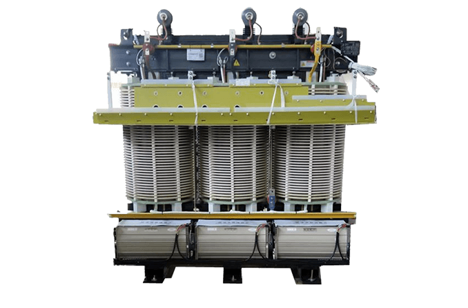
Facility Isolation Transformer
Series: FIS Series
The design maps voltage, phase, kVA, grounding, harmonics, enclosure and ambient conditions to an isolation configuration that fits the facility and its application boundary. cnbbelc converts those inputs into approved drawings, controlled manufacturing steps and routine test records for a made-to-order transformer. Independent windings provide galvanic separation while regulation, surge protection and specialist compliance remain separate engineering choices.
- Rated capacity100 kVA–12 MVA
- Primary voltageUp to 35 kV
- Phase and frequencyThree-phase, 50/60 Hz
- Supply positionMade to order
- MOQ1 set
- CustomizationVoltage, impedance, vector group, shielding, enclosure and dimensions
Site Inputs That Determine The Facility Isolation Transformer
The electrical system and connected load define the starting point. The same kVA rating can require a different winding, shielding, thermal or enclosure design when grounding, harmonics or the installation environment changes.
| Site input | Configuration decision | Operational consequence |
|---|---|---|
| Input/output voltage, three-phase kVA, 50 or 60 Hz, vector group and neutral | Turns ratio, conductor size, winding connection and terminal arrangement | The transformer matches the facility bus and downstream equipment without treating voltage conversion as a generic default. |
| Variable-frequency drives, rectifiers, UPS systems or other non-linear loads | Declared harmonic spectrum, impedance target, thermal margin and winding geometry | Loss and temperature-rise calculations reflect the actual current waveform instead of a purely linear load. |
| Ground loops, common-mode noise or sensitive instrumentation | Separately derived secondary, grounding plan and optional electrostatic shield | Galvanic separation breaks the direct conductive path; shielding can reduce capacitive coupling when it is specified and grounded correctly. |
| Dust, moisture, salt mist, altitude, indoor or outdoor placement and ventilation | Enclosure, insulation system, cooling method, corrosion protection and clearances | The installation preserves cooling and insulation performance under the stated site conditions. |
| Patient-connected medical areas or hazardous locations | Separate leakage-current, insulation, enclosure and product-standard review | A general facility transformer is not presented as automatically medical grade or suitable for a hazardous location. |
From Facility Data To Approved Drawings And Test Records
Quotation inputs
Rated kVA, input and output voltage, frequency, phase, vector group, impedance, load type, harmonic data, insulation class, cooling, enclosure, maximum dimensions, terminal direction, altitude and ambient conditions establish the electrical and mechanical scope.
Design approval
Contract review converts the application data into the winding arrangement, insulation coordination, losses, temperature-rise basis, enclosure and outline drawing. Production starts after the agreed technical schedule and drawing are approved.
Manufacture and release
Incoming materials, coils, insulation parts, core manufacture and assembly have inspection points. Routine release can cover winding resistance, ratio and vector group, no-load and load losses, short-circuit impedance, insulation resistance, dielectric tests and partial discharge when applicable. The shipment includes the approved drawings, nameplate data and routine test record.
What Galvanic Isolation Does And Does Not Do
An isolation transformer has independent primary and secondary windings. Alternating current in the primary creates magnetic flux in the core, and that flux induces voltage in the secondary without a direct conductive connection between the two circuits. This arrangement can establish a separately derived secondary system and interrupt a ground-loop path.
Isolation does not automatically hold the output at a constant voltage, remove every harmonic or stop every surge. Voltage regulation, surge protective devices, harmonic mitigation and an electrostatic shield remain separate design choices. Patient-connected medical equipment also needs the applicable leakage-current and safety-standard review; the general FIS Series specification alone does not establish medical compliance.
Specifications
Final ratings follow the approved technical schedule and single-line diagram.
| Product name | Facility Isolation Transformer |
|---|---|
| Series | FIS Series |
| Product category | Three-phase dry-type isolation transformer |
| Rated capacity | 100 kVA–12 MVA |
| Rated voltage | Primary up to 35 kV; input/output ratio configured to the approved single-line diagram |
| Core, windings and insulation | Grain-oriented silicon-steel core; copper or aluminum windings; cast-resin or VPI insulation by project |
| Connections | Copper-bar or cable-terminal connections; vector group and neutral brought out to the approved drawing |
| Design and test basis | IEC 60076-1 and IEC 60076-11; IEEE dry-type requirements when specified in the contract |
| Traceability | Nameplate, serial number, approved drawings, routine test report and outgoing inspection record |
| Packing unit | 1 transformer per export wooden case or steel skid with moisture barrier |
Performance And Installation Conditions
These standard conditions establish the quotation baseline. Declare non-linear loads and non-standard environments so the thermal, insulation and enclosure design can be adjusted.
Ordering And Delivery
Commercial terms are a starting basis for a made-to-order FIS Series transformer and are finalized with the approved specification.
- MOQ1 set
- First articlePaid first-article transformer; outline drawing and electrical data approved before manufacture
- First-article lead time25–35 working days after drawing approval
- Production lead time45–70 working days after drawing approval and deposit
- Starting price and availabilityFrom USD 8,900 per set, EXW Shanghai; PreOrder / made to order
- PackagingExport wooden case or steel skid with moisture barrier, terminal protection and lifting marks
- Payment terms30% deposit with order and 70% before shipment after routine-test review
- Shipping supportSea freight, air freight for small units, or buyer-arranged pickup; export documents supplied
Manufacturer And Production Control
The facility transformer is engineered and released as a project-specific product.
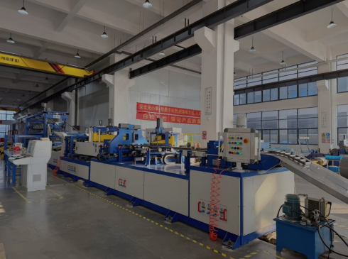
Shanghai Beibian Technology Co., Ltd.
Shanghai Beibian designs and manufactures special transformers and supporting power-conversion products. The order flow covers contract review, design, incoming inspection, winding and insulation processing, core manufacture, assembly, routine testing, outgoing inspection, packing and shipment.
- Manufacturing locations recorded in Shanghai Songjiang, Wenzhou and Jinan
- Configurable capacity, voltage, windings, impedance, insulation, cooling and enclosure
- Cast-resin and VPI dry-type insulation processes selected by application
- Approved drawings, nameplate data, routine test record and export documentation
Standards And Compliance Documents
Request the current certificate, declaration and test-document set for the exact model and destination market during quotation review.
Document set named for review
ISO management-system, CE, ETL, UL, RoHS and REACH documentation is available for scope review. The applicable product, legal entity, standard, certificate number and validity must match the quoted transformer and destination market.
- IEC 60076-1 and IEC 60076-11Design and routine-test basis when specified
- Routine electrical test reportIssued for the delivered serial number
- CE, ETL and UL documentsScope reviewed against the order before use
- RoHS and REACH documentsMaterial and market scope reviewed with the quotation
Send The Facility Electrical Schedule
- Phone: +86 152 6708 2061
- Email: [email protected]
- WhatsApp: +86 152 6708 2061
- Address: 333 Minta Road, Songjiang District, Shanghai