
 BBELC

electric isolation transformer
cnbbelc engineers three-phase dry-type transformers that transfer AC power between separate windings while matching the voltage and installation needs of the load. Choose an industrial design or a shore-power configuration, then define the grounding, cooling, enclosure and test requirements for your project.

Dry-Type Isolation Transformer
Electrical Isolation and Voltage Conversion
An isolation transformer uses separate primary and secondary windings. AC power crosses the magnetic core without a direct conductive path between the two circuits. The winding ratio can maintain the nominal voltage or change it to suit downstream equipment.
Winding separation does not define how the secondary is grounded. The system designer must specify the secondary connection, neutral, bonding and protective devices. If common-mode noise control is required, specify an electrostatic shield and its grounding point; winding isolation alone does not guarantee a particular noise attenuation level.
Define the Electrical Duty and Installation
Start with the source, the connected load and the electrical function the transformer must perform. These inputs determine the winding design and physical arrangement.
| Project input | What it determines |
|---|---|
| Primary and secondary voltage, phase and frequency | Winding ratio, connection and insulation design |
| Continuous kVA, inrush and nonlinear load duty | Thermal rating, impedance and cooling approach |
| Grounding, neutral and shielding requirements | Secondary interface and optional electrostatic shield |
| Ambient temperature, altitude, humidity and contaminants | Insulation, ventilation and enclosure details |
| Space, cable entry and handling route | Outline dimensions, terminals and lifting arrangement |
For a drive or rectifier load, include the converter topology and duty cycle. For shore power, include the vessel-side interface and site exposure so the transformer can be coordinated with the supply system.
Dry-Type Isolation Transformer Options
The two designs below follow the supplied product list. Final ratings and construction are confirmed against the approved electrical schedule.
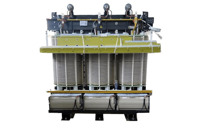
Dry-Type Isolation Transformer
Project-engineered three-phase isolation and voltage conversion for industrial and commercial distribution systems.
- Rated power100 kVA to 12 MVA
- Primary voltageUp to 35 kV
- Insulation classF or H
Dry-Type Isolation Transformer for Shore Power
Dry-type isolation for port and vessel power interfaces, with voltage and environmental protection specified for the site.
- Frequency50 or 60 Hz
- Primary options6 or 6.6 kV by design
- Rated powerUp to 12 MVA
Match the Design to the Power System
Industrial and commercial distribution
The general dry-type design can provide an isolated secondary for plant equipment, controls, commercial loads or other engineered supplies. The load and grounding scheme determine the voltage ratio, vector group, taps and enclosure; the transformer is coordinated with upstream and downstream protection.
Marine and shore-power interfaces
A shore-power transformer works within the port supply and vessel connection system. Its design must account for voltage and frequency, bonding, enclosure location, humidity and salt exposure. The customer and manufacturer can then define protective treatment and the interfaces to converters or rectifier transformers.
Approve the Design and Test Scope
Before production, align the electrical schedule with the outline drawing, terminal arrangement, cooling method and installation clearances. Review the transformer rating and site interfaces alongside the system single-line diagram.
cnbbelc's finished-product process includes electrical testing and outgoing quality inspection. Agree the applicable routine-test schedule for the ordered configuration, such as winding resistance, voltage ratio and vector group, insulation resistance, losses, impedance and dielectric tests. Record any witness, partial-discharge or project-specific tests in the purchase specification so the report matches the approved design.
Send project requirementsRequest an Engineered Quote
- Phone: 8615267082061
- Email: [email protected]
- WhatsApp: 8615267082061
- Address: 333 Minta Road, Songjiang District, Shanghai