
 BBELC

Electric Distribution Transformer
Three-Phase Cast Resin Dry Type
Step medium-voltage power down for indoor commercial and industrial loads with a three-phase cast-resin transformer engineered around your voltage, capacity, impedance, cooling, and installation requirements.
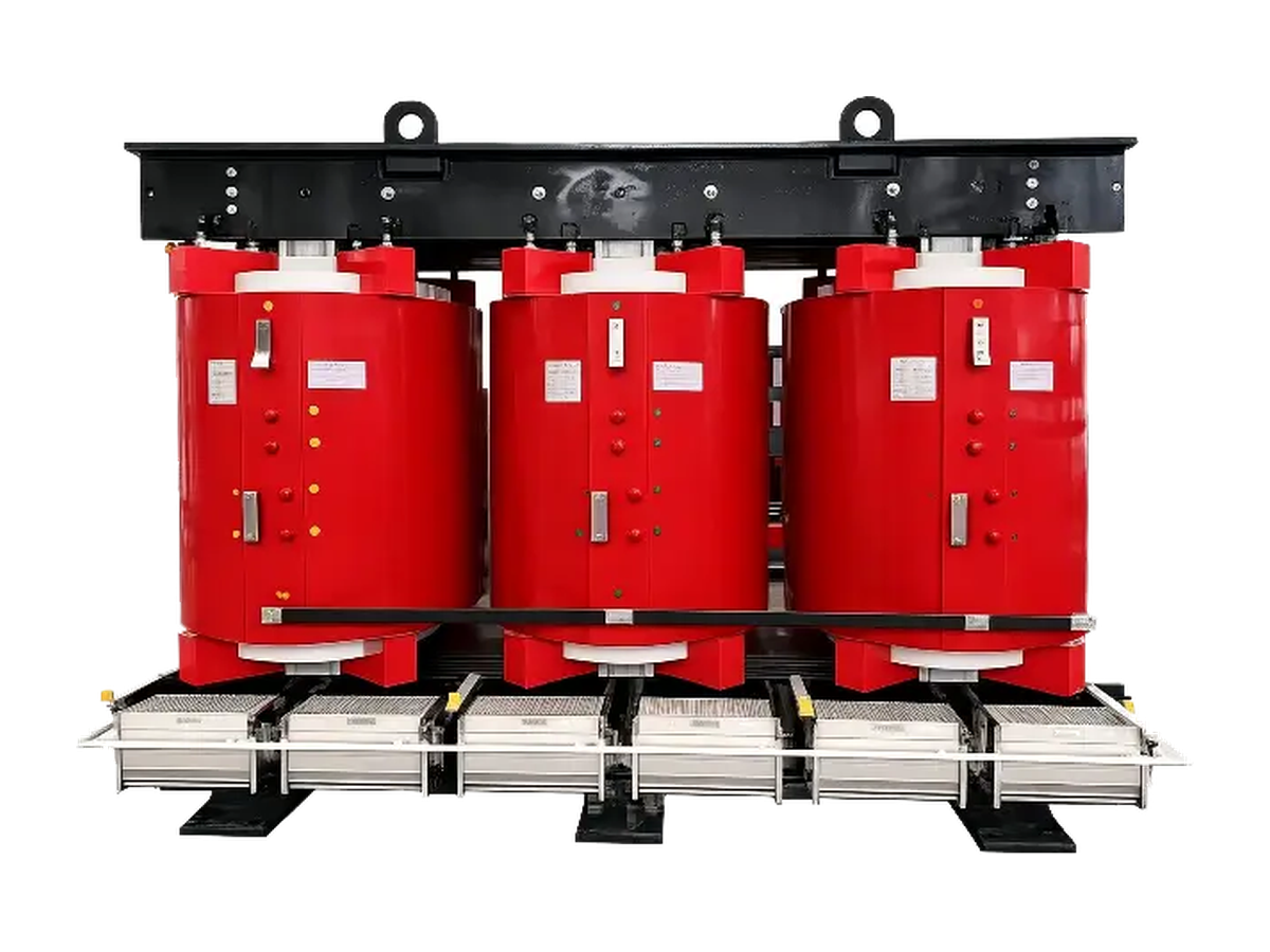
Three-Phase Cast Resin Dry-Type Distribution Transformer
Three-phase cast-resin dry-type distribution transformer in an open black frame.
Where an Electric Distribution Transformer Fits
An electric distribution transformer performs the final major voltage reduction near the loads it serves. It accepts power at the project’s primary distribution voltage and supplies the lower utilization voltage required by building systems, production equipment, or other local loads.
The transformer transfers energy between electrically isolated windings through a magnetic core. The turns ratio establishes the nominal voltage conversion, while winding current, insulation level, temperature rise, and cooling determine how much apparent power the unit can carry. Its kVA rating therefore represents voltage and current capacity; it does not equal the load’s kW demand unless power factor is included.
Shanghai Beibian Technology Co., Ltd. designs and manufactures transformers for power conversion applications. For indoor distribution projects, BBELC offers a three-phase cast-resin dry-type design whose voltage, capacity, impedance, enclosure, and cooling can be matched to the electrical system and site.
Why Cast-Resin Dry Type Fits Indoor Distribution
A cast-resin dry-type transformer encapsulates its windings in solid resin and uses air for cooling, so the installation does not need an insulating-liquid system. This structure suits many indoor substations in commercial buildings, industrial plants, hospitals, offices, and public infrastructure where available space, ventilation, and building coordination shape the equipment choice.
The absence of insulating liquid changes the surrounding work. Operators focus on airflow, dust, condensation, winding surfaces, connections, temperature sensors, and fans where fitted. A liquid-immersed transformer adds liquid containment, leakage checks, liquid condition, pressure accessories, and related fire-protection provisions. The correct choice follows the site layout, environmental exposure, fire strategy, maintenance practice, and required electrical performance.
Cast resin does not remove the need to specify the environment. Outdoor exposure, conductive dust, salt, corrosive gas, high humidity, condensation, high altitude, and unusual ambient temperature can require a suitable enclosure, coating, increased clearances, revised cooling, or a different transformer construction.
Featured Electric Distribution Transformer
Open-frame SCB14 cast-resin transformer showing three encapsulated phase windings and base-mounted fans.
Three-Phase Cast Resin Dry-Type Distribution Transformer
This SCB14-series transformer combines a three-phase distribution design with epoxy-resin cast windings for indoor medium-to-low-voltage service. It can be configured for the project’s voltage, capacity, impedance, enclosure, and cooling requirements.
Core Specifications
- SeriesSCB14, epoxy-resin cast
- Rated capacity100 kVA to 20 MVA
- Rated voltageUp to 35 kV
- Insulation classF or H
- Configurable itemsVoltage, capacity, impedance, enclosure, and cooling
Select Ratings from the Load and System
Start capacity selection with the highest credible operating load, including simultaneous demand, motor starting, future expansion, redundancy states, and any permitted short-duration overload. For a three-phase system, kVA follows line voltage and line current; the usable kW also depends on the connected load’s power factor. Persistent phase imbalance or nonlinear current can heat one winding more than the total three-phase kVA suggests.
Primary and secondary voltages must match the source, load, grounding arrangement, and available tap positions. Frequency sets the magnetic design basis, so a 50 Hz and a 60 Hz requirement cannot be treated as interchangeable without confirmation. The vector group fixes phase displacement and neutral availability, which affects grounding, protection, harmonics, and compatibility with transformers that may operate in parallel.
Percentage impedance influences both fault current and voltage regulation. A higher value generally limits available short-circuit current but increases voltage drop under load; a lower value can improve regulation while raising fault duty. Parallel units also need compatible ratios, tap positions, phase relationships, and impedance so they share load without excessive circulating current.
Send the expected load profile and waveform with the electrical data. Harmonic-rich loads add winding and stray losses, and large motor or transformer inrush affects protection coordination. A useful specification therefore includes rated and maximum system voltage, frequency, kVA, vector group, grounding, taps, impedance, insulation level, short-circuit conditions, and the load’s harmonic and imbalance data.
Coordinate the Room, Enclosure, and Cooling
The room must remove the transformer’s no-load and load losses as heat. Cool air should reach the lower air paths and warm air should leave above the unit without recirculating through an obstructed duct or enclosure. If forced-air fans provide additional capacity, the specification should state the rating available with fans on and the rating that remains if a fan or its power supply is unavailable.
An enclosure affects more than contact protection. Its ingress protection, louvers, filters, cable entry, and clearances change airflow, temperature rise, sound transmission, dimensions, and maintenance access. Select the enclosure together with the transformer thermal design rather than adding it after the winding and cooling arrangement has been fixed.
Provide the installation altitude, minimum and maximum ambient temperature, humidity and condensation conditions, dust or corrosive contaminants, seismic requirement, floor loading, transport route, terminal direction, cable or bus connection, and service clearances. These inputs allow the winding insulation, air clearances, cooling method, enclosure, and physical layout to be designed as one system.
Compare Losses Against the Operating Profile
No-load loss continues whenever the transformer is energized, even when the secondary carries little or no load. Load loss rises mainly with the square of current, so it becomes more influential during heavily loaded periods. Fans, controls, harmonic currents, and other accessories can add consumption beyond the two headline loss values.
Compare alternatives at the same voltage, capacity, reference temperature, cooling state, load factor, power factor, and measurement method. Then apply no-load and load-loss data to the expected hourly or seasonal load profile. A unit with a lower full-load loss may not produce the lowest annual energy use when it spends most of its life lightly loaded, while a continuously loaded unit gives greater weight to winding losses.
Purchase price, energy loss, cooling demand, maintenance access, and the cost of an outage all influence the ownership decision. This comparison gives the design team a practical basis for balancing conductor and core material, transformer size, first cost, and operating cost.
Verify the Finished Transformer Before Shipment
Finished-product testing connects the approved design to the individual transformer being shipped. Shanghai Beibian’s production flow includes finished-transformer testing and outgoing quality inspection after assembly.
The project test schedule can include visual inspection, insulation resistance, winding resistance, voltage ratio and vector group, no-load current and loss, load loss and short-circuit impedance, applied-voltage withstand, induced-voltage withstand, and partial-discharge measurement. Each result should identify the transformer, tap position, temperature or correction basis, test voltage, duration, and acceptance value needed to interpret it.
Review the nameplate, connection diagram, outline drawing, terminal arrangement, accessory list, and test report together. This confirms that the tested electrical configuration matches the equipment dimensions, cooling arrangement, and interfaces approved for the site.
Specify Your Electric Distribution Transformer
Share the system voltage, required secondary voltage, capacity, frequency, vector group, impedance target, load profile, installation environment, enclosure, cooling method, quantity, and delivery destination. BBELC will use these inputs to prepare a project-specific transformer selection and quotation.
- Phone: +86 152 6708 2061
- Email: [email protected]
- WhatsApp: +86 152 6708 2061
- Address: 333 Minta Road, Songjiang District, Shanghai